Using Bays you can create a Ladder Beam. Ladder Beams are used with Kwikstage and are slightly different from Bridging Beams. We will need to use the Material Master to change a Ladder Beam into a Bridging Beam. This is because the Material LadderBeam doesn't show up on the drawing, so has to be changed to a BridgingBeam
Before we begin, we need to set up the Material Master to enable Ladder Beams so that we can use them in our design.
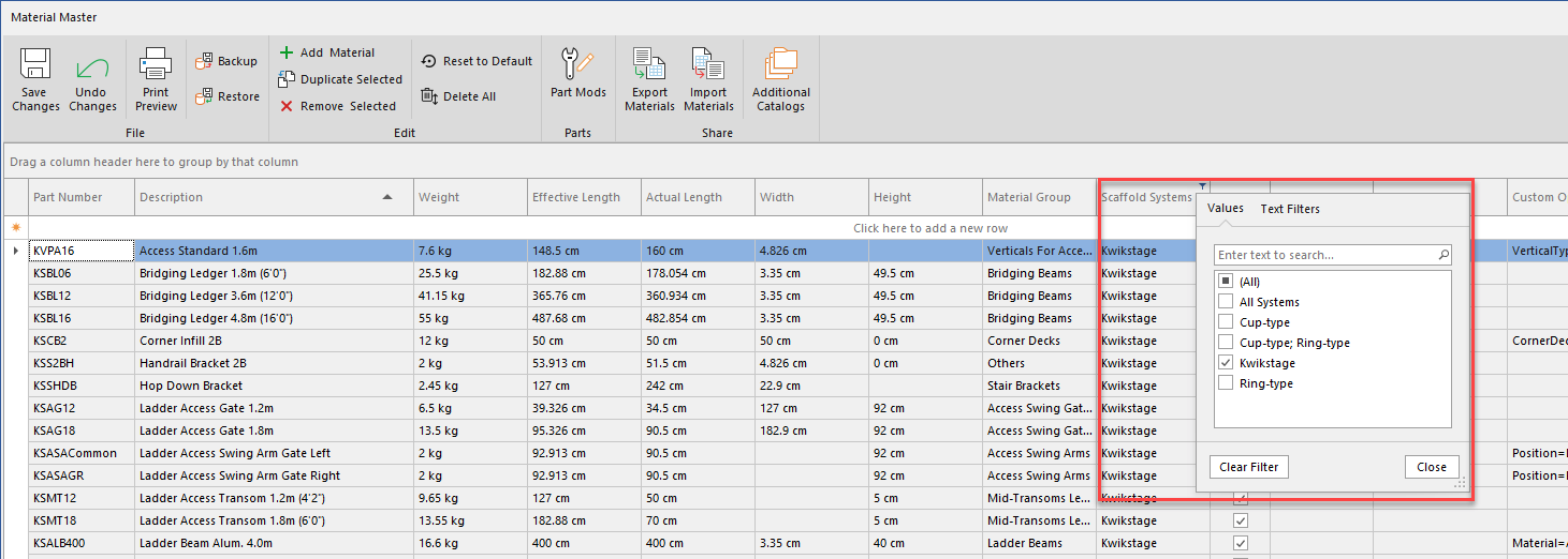
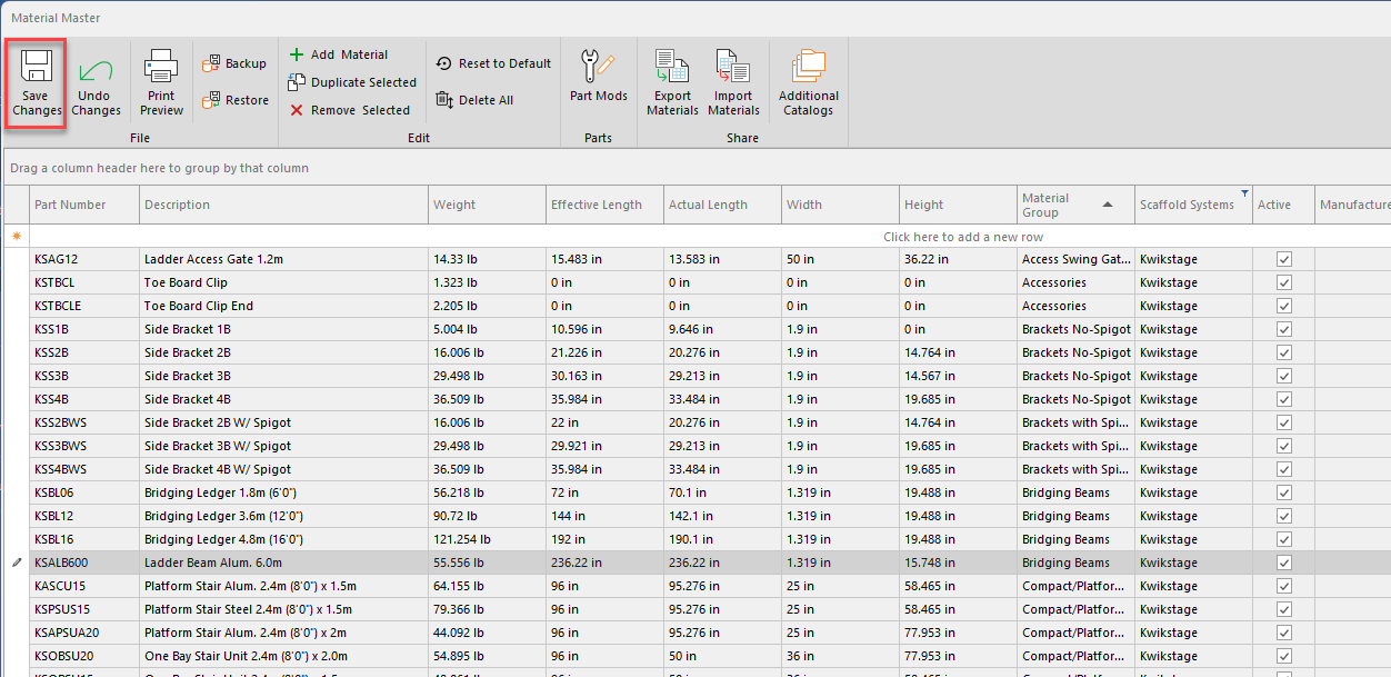
In the Material Master, select the key icon on the column heading of the Supported System column.
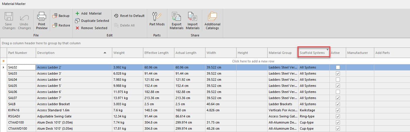
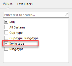
From the list of options provided, select to filter KWIK. This will show only parts assigned the KWIK Supported Systems
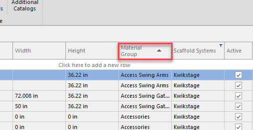
Click the Material Groups heading to order the Material Group alphabetically to make it easier to find the group we need (Ladder Beams).
Change the required Ladder Beams to Bridging Beams by clicking in the Material Group cell and typing "Bridging Beams".
Note: Bridging Beams will be auto-filled once enough characters have been entered.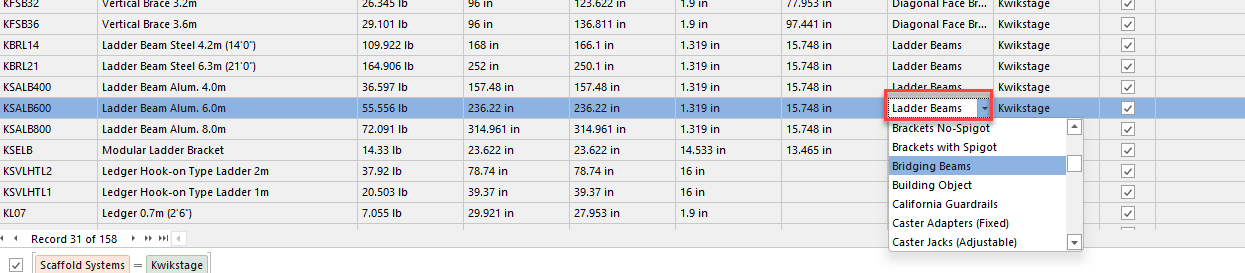
We need to set up the Material Master to tell it is using a ladder beam, so in the custom settings we need to specify Bridging Beam under the Name column and in the Value column we are going to specify "LadderBeam"Select a cell from the Custom Options column of a Ladder Beam
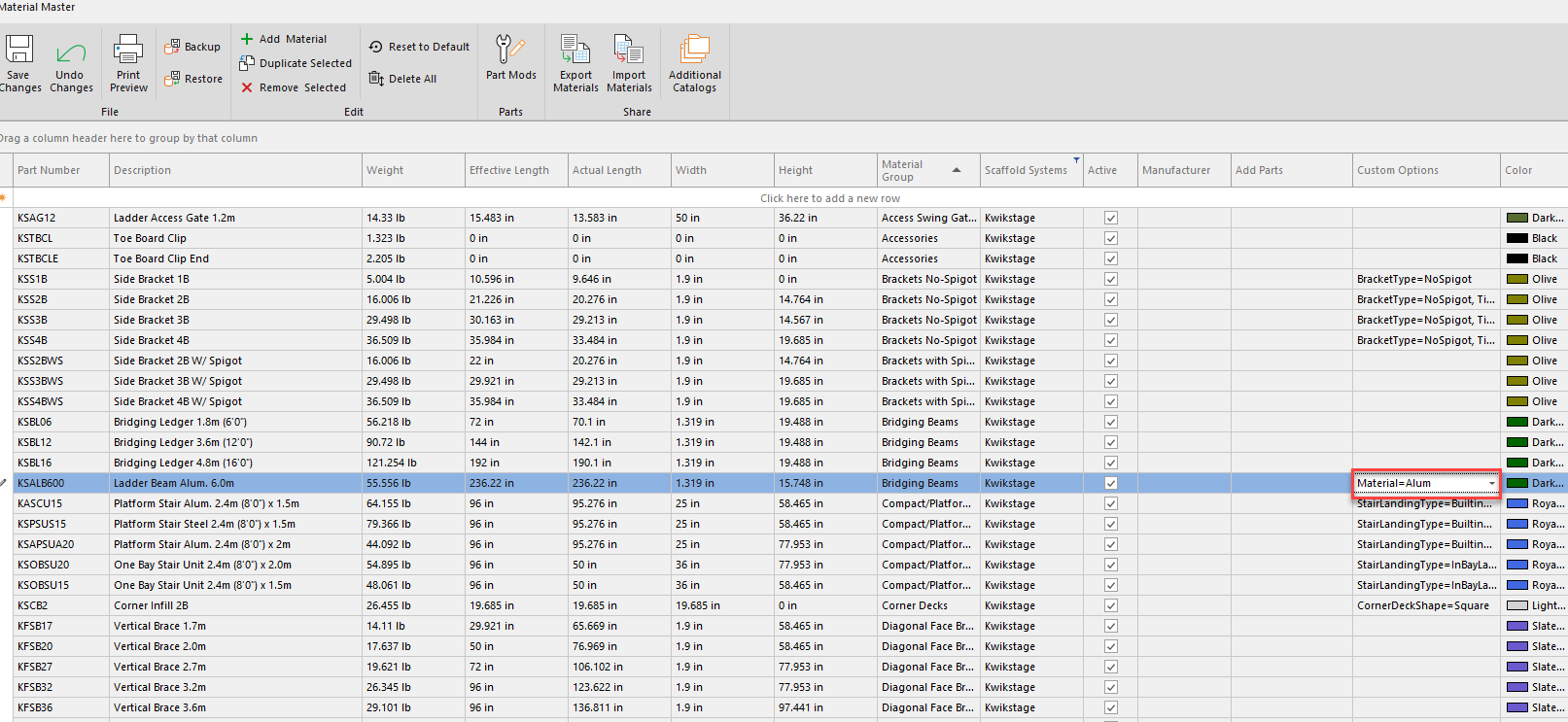
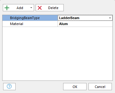
In the Custom Options dialog, click and set the Name as BridgingBeamType and set Value as LadderBeam.
Click OK.
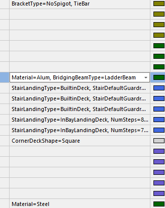
The custom options will be added to the Ladder Beams.
If you want to automatically display clamps to the beam, we can add the Right-Angle Bolt Clamp to the Custom Options of the Ladder Beam.Change the filter to ensure all systems are displayed.
Click the cell Add Parts of the Ladder Beans.
Locate the part, add it to the part by clicking the checkbox and enter the Quantity.
When done, click Save and close the Material Master
You can now begin creating your Scaffold
Creating your Scaffold
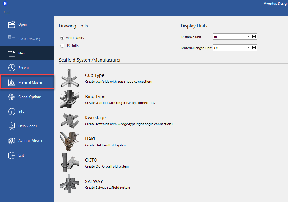
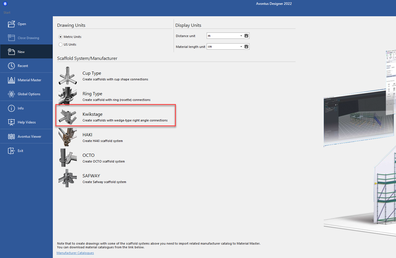
From the main screen, select the Scaffold system to use. As we're using Ladder Beams, we have to select Kwikstage.
Drag a Bay to the design screen
Add some levels to the Bay. We will add one level.
Select to copy the Scaffold Bay to the right. We will do this three times.
Drag one of the Scaffolds to the side, we will make changes to this later.
Select the bay in the center and change this to a Ladder Beam by clicking TB and selecting the Ladder Beam.
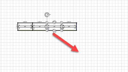
Next center the Ladder Beam between the two bays
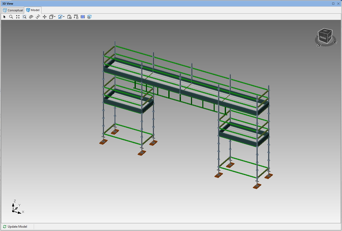
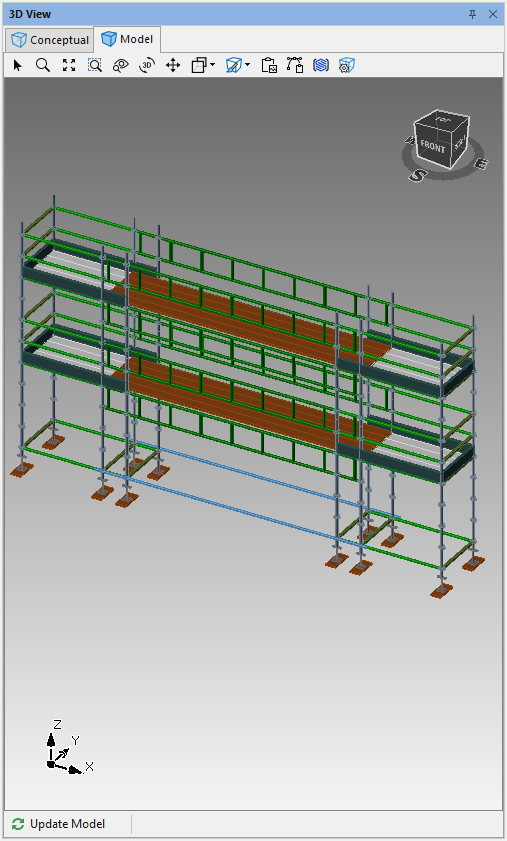
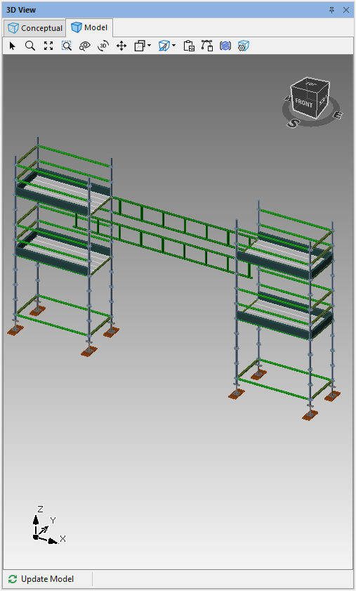
Your 3D model should look something like this
We will next remove the unwanted levels and the verticals. For display purposes, and material count we will also switch off the left and right sides of the Ladder BaySelect the Bridging Beam and select Bay Details
In Bay Details, select Vertical and add a tick to skip all Verticals
Click Sides, skip the L and R side then click Apply
On the Bridging beam, unplank every level
Skip the bottom two levels by putting a tick in them
Your design will look like this
Select the Bay you pulled out earlier and click Side Settings
Disable all Screwjacks
Click OK
On the same bay, and remove the bottom two levels
Drag the bay into place
Select the Bay and click R to add a bay to the right
Click Rejoin Bays
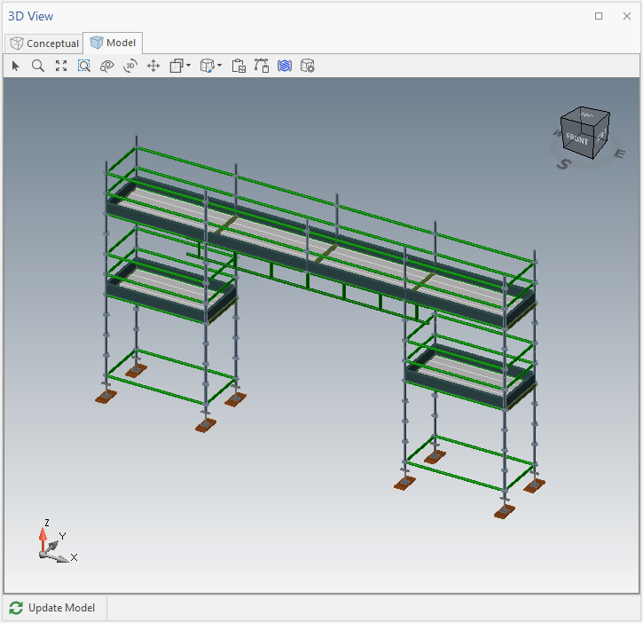
The result will look like this