In this tutorial you will learn how to use the new Beam object to create a sloped scaffold deck and guardrails with parts that are accurately counted in the Bill of Materials (BOM).
Click here to see a video version of creating a ramp
Create and Configure a Bay
The first step in creating a Scaffold with a sloped deck ramp is creating and configuring the Bay that will house the ramp.
To create and configure a Bay:
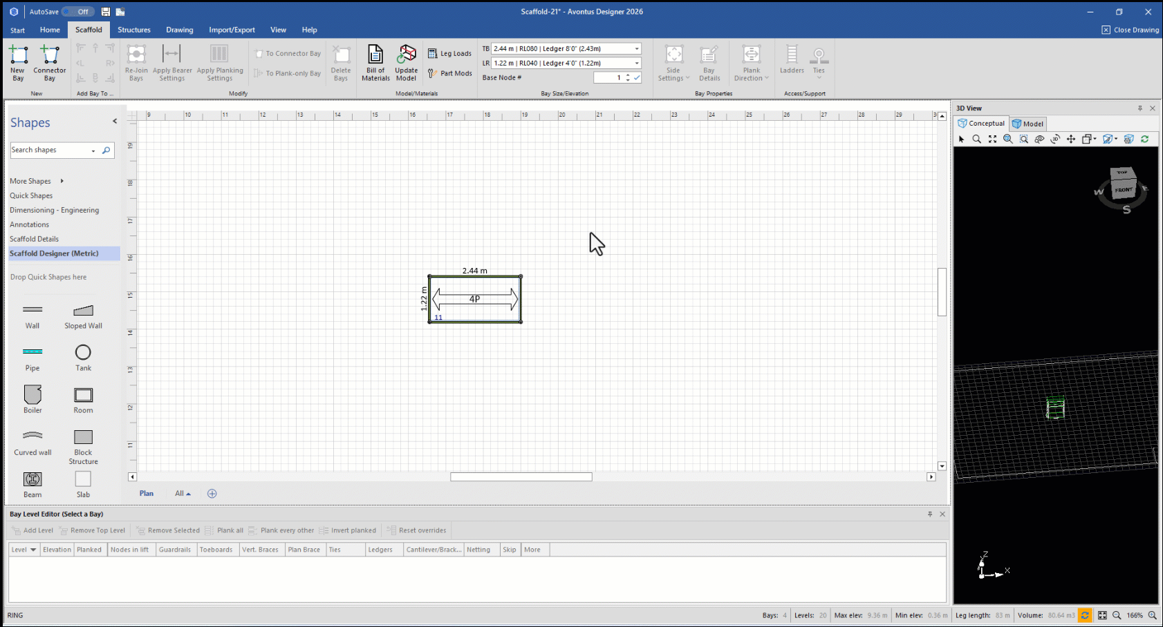
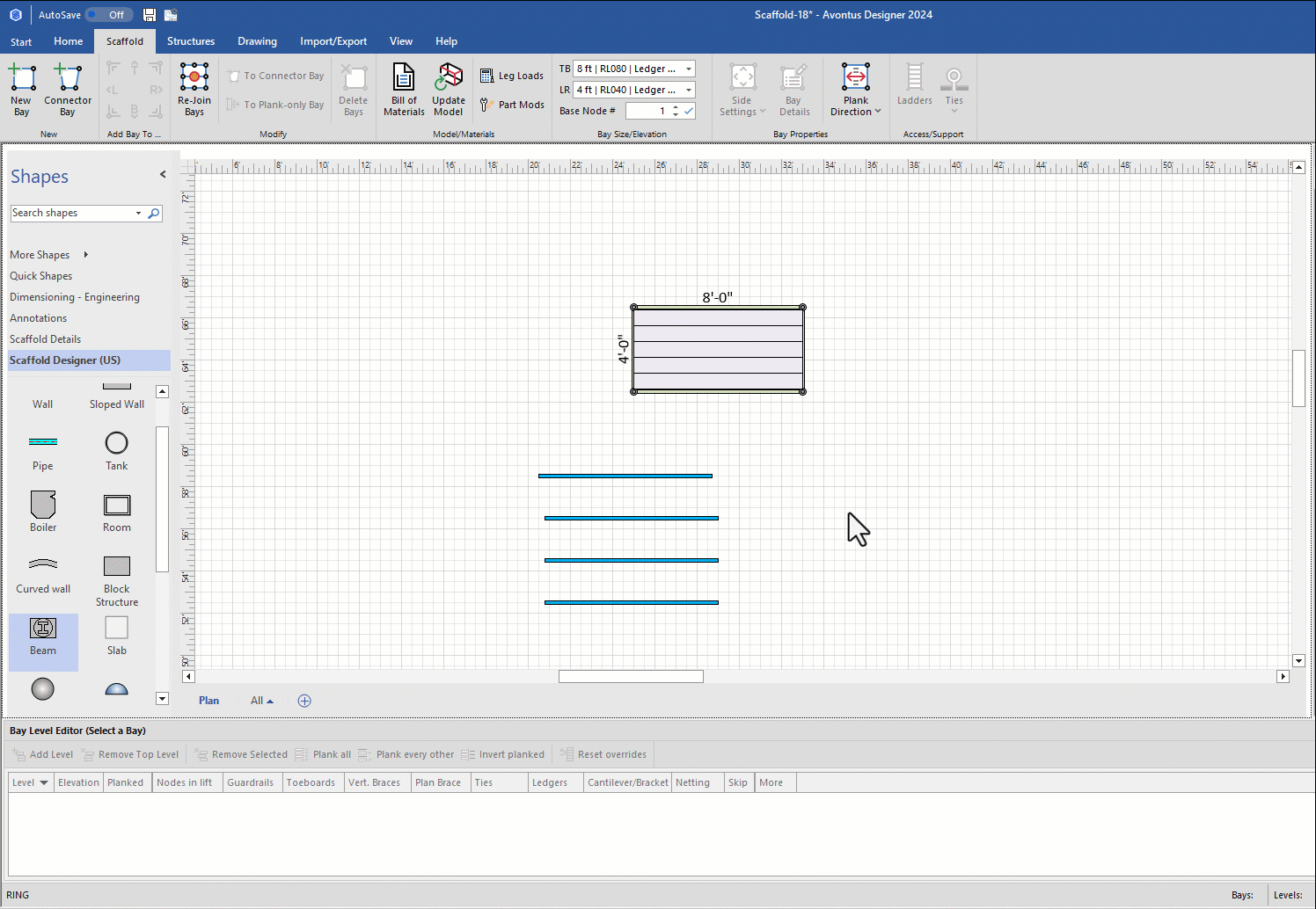
Click the Scaffold tab, then click New Bay and drag the new Bay onto the Drawing Page.
Note: If required, enable the Bay Level Editor
Click the Planked checkbox in the Level 1 row, to remove its check.
Double-click in the Nodes in Lift text field for Level 0, enter 1 and click the check to the right of the field.
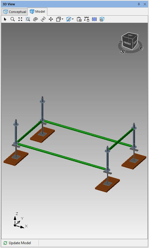
Click Ledgers in Level 0
Click R in the popup that appears to disable the right ledger
Click away from the pop-up or select

Click Ledgers in Level 1
Click T, L and B in the popup that appears to disable those ledgers.
Click away from the pop-up or select
.gif)
The result looks like this:
As necessary, click the Bay, to select it.
Click the Bay Details dropdown.
Then click the Verticals tab.
Double-click the appropriate text fields in the Extend Top row and enter the following:
T/R text field: 2
T/L text field: 1
B/L text field: 1
B/R text field: 2
Click Apply
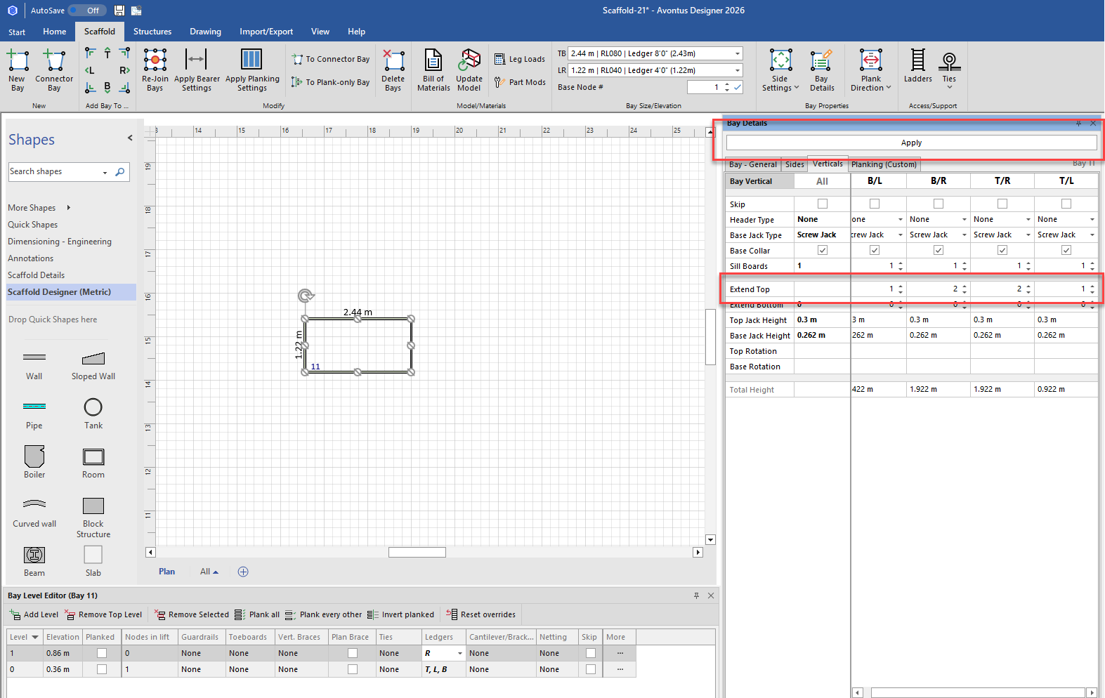
The result looks like this:
Create and Configure the Planks
Step two is to create a plank piece that can be used to cover the Bay with copies of the plank. However, to create planks for the sloped deck, start with a Beam.
To create and configure the planks:
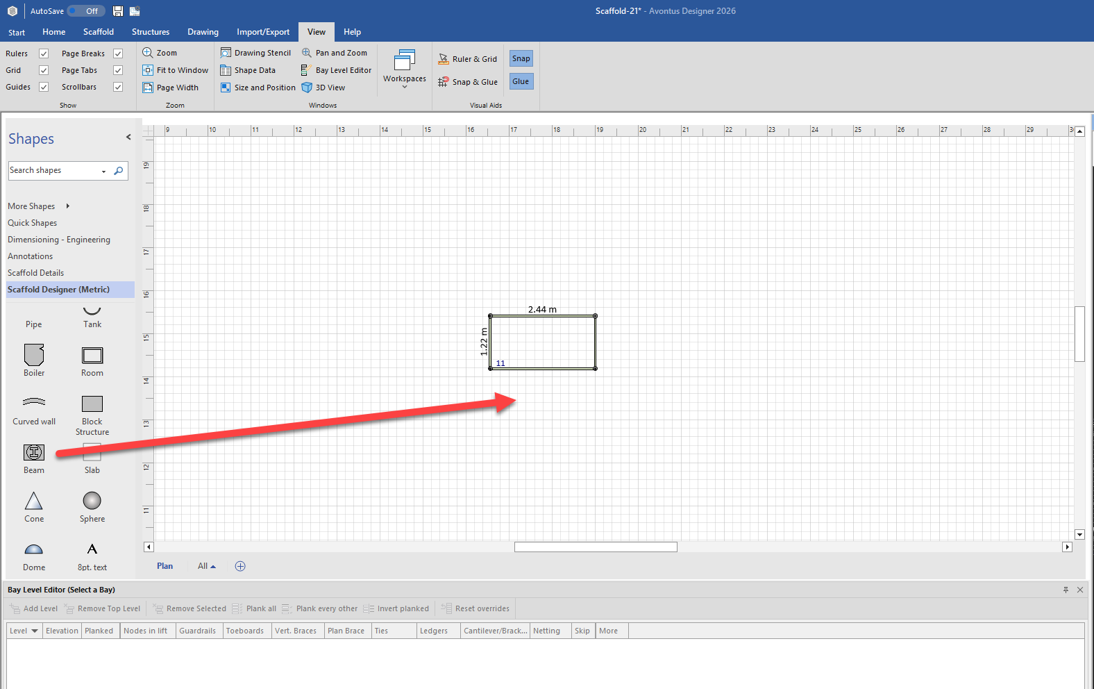
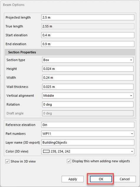
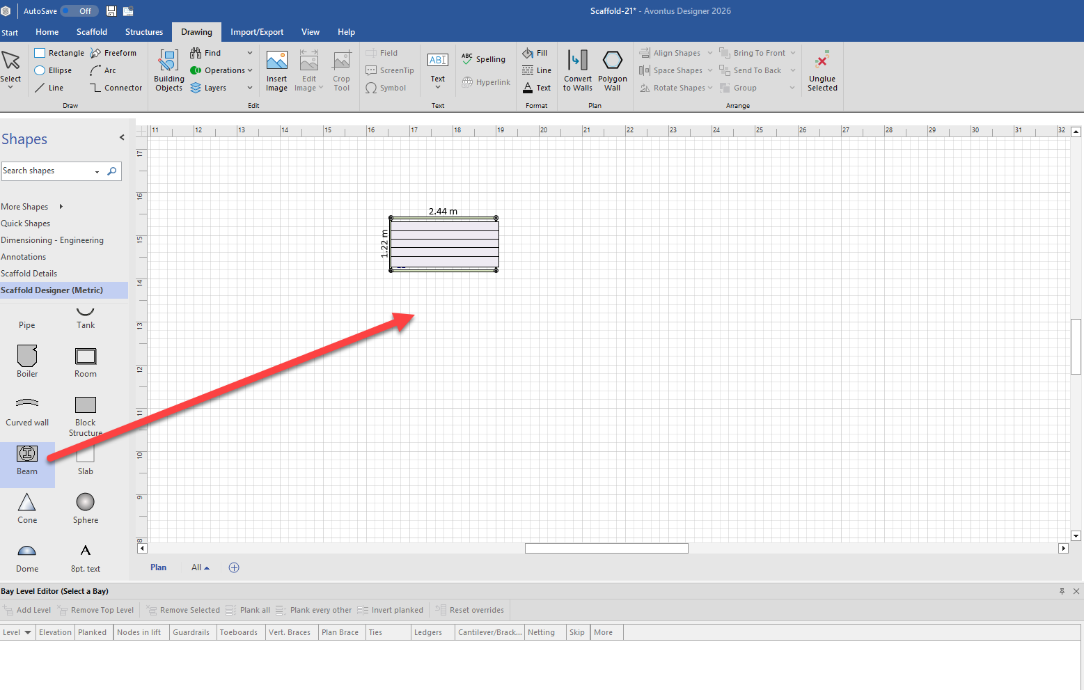
Click the Beam object and drag it onto the Drawing Page.
Double-click the Beam.
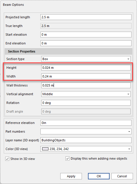
The Shape Data dialog appears.Click the Section Type dropdown and select Box.
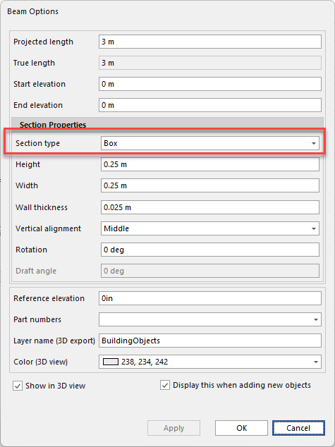
Click in the Projected Length text field and enter the length of the Bay.
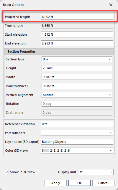
Click in the Height text field and enter the thickness of plank used.
Click in the Width text field and enter the width of plank used.
Set slope of the Beam to match that of the deck. (This may take some trial and error.)
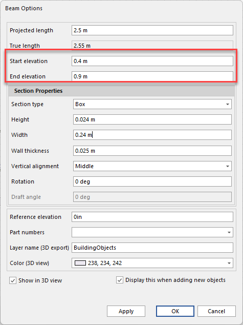
Click in the Start Elevation text field and enter the start elevation.
Click in the End Elevation text field and enter the end elevation.
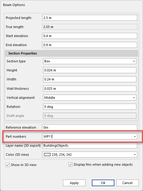
Click in the Part Number text field and enter the Plank part number from the Material Master.
This makes the Beam recognizable as a plank in the Bill of Materials.
Click OK.
Change the color of the plank to match the plank color (This is optional).
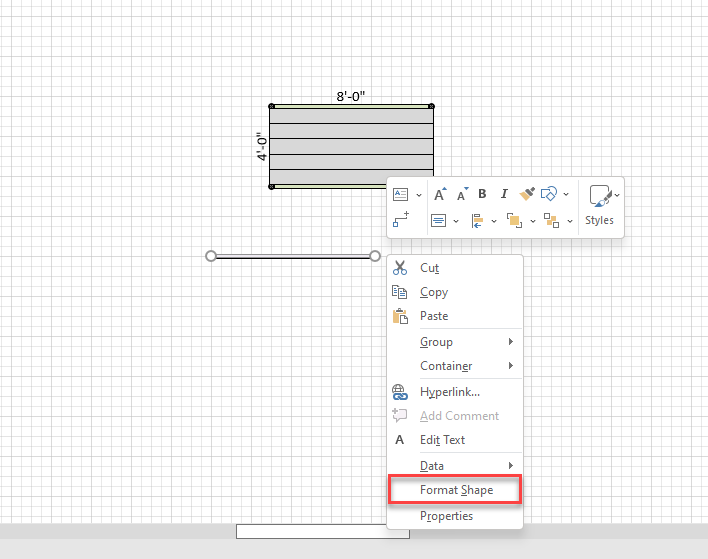
Right-click the Beam and select Format Shapes from the menu that appears..

The Format Shapes dialog appears.Click the Fill triangle, then click the Solid Fill radio button.
Click the paint bucket icon (
 ) and select the desired colour
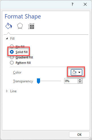
Click OK.
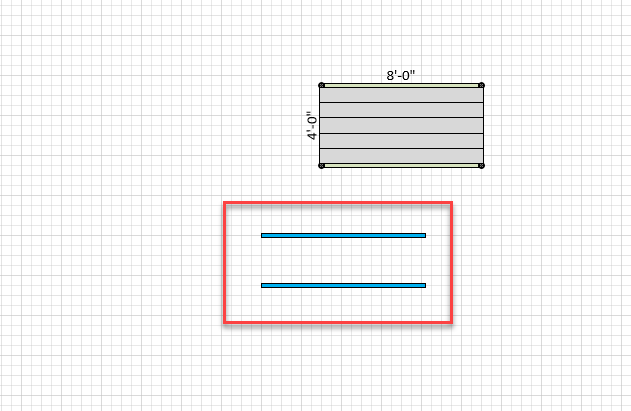
Copy and Paste the planks to create enough to fill the bay
Line them and group them if you wish
Click and drag the planks into place on the Bay.
The result looks like this on the plan view
.gif)
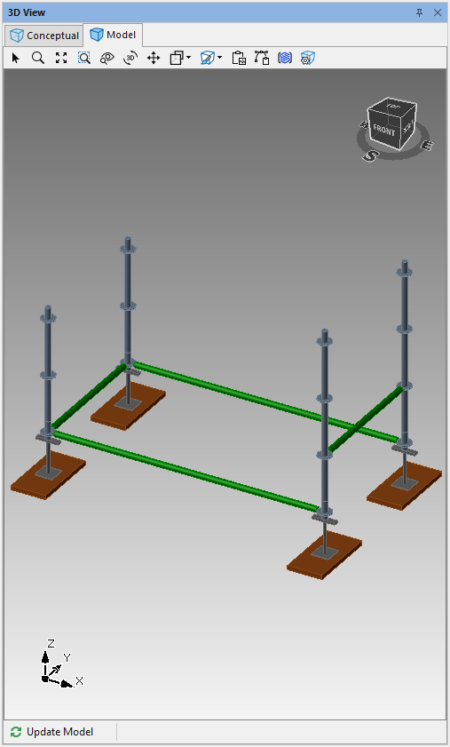
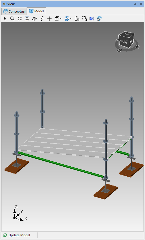
In the model view, the model looks like this.
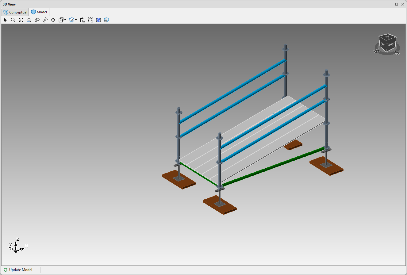
Create and Configure the Guardrails
The final step is to create and configure a guardrail, and then create enough duplicates to fill the required places. However, to create guardrails for the sloped deck, again, start with a Beam.
To create and configure the guardrails:
Click the Beam object and drag it onto the Drawing Page.
Double-click the Beam.
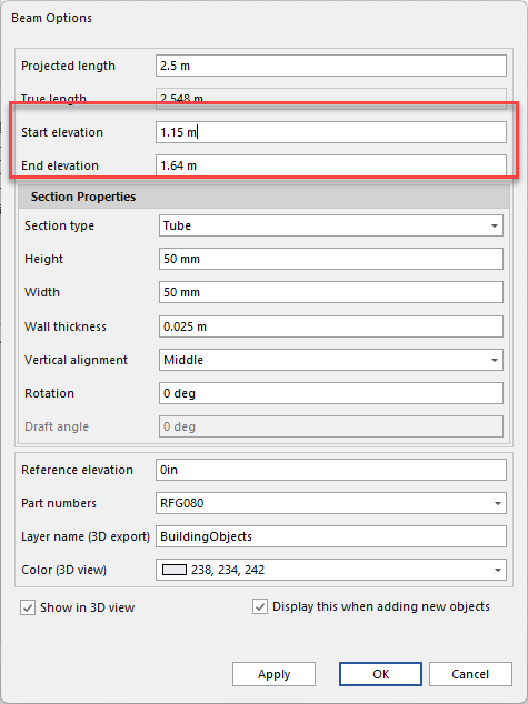
The Shape Data dialog appears.Click the Section Type dropdown and select Tube.
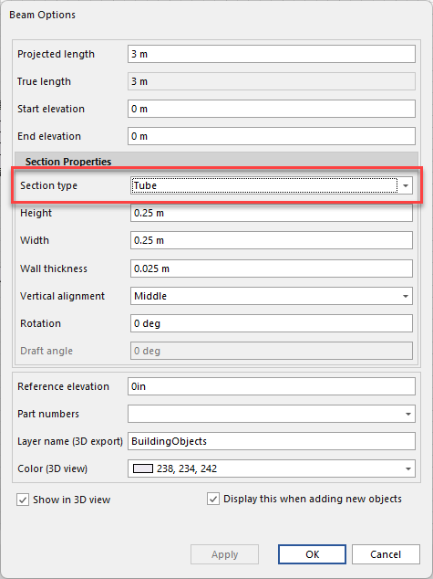
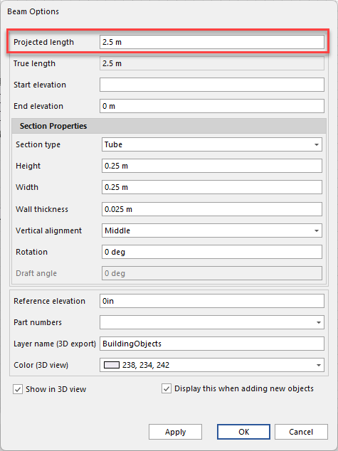
Click in the Length text field and enter the length of the Bay.
Click in the Width text field and enter 50 mm.
Click in the Height text field and enter 50 mm.

Set slope of the Beam to match that of the deck. (This may take some trial and error.)
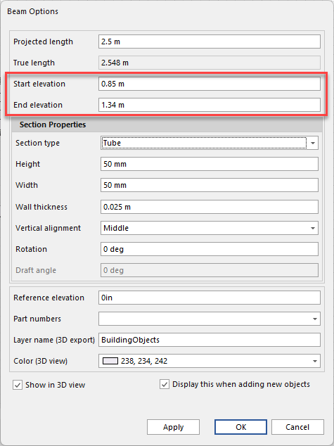
Click in the Start Elevation text field and enter the start elevation for a lower guardrail.
Click in the End Elevation text field and enter the end elevation for a lower guardrail.
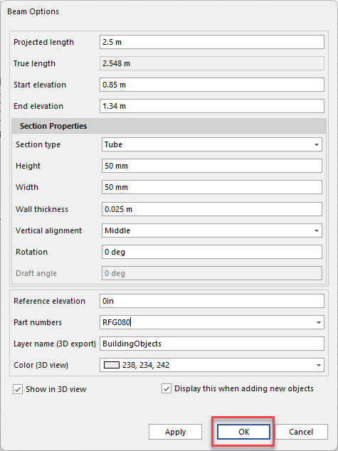
Click in the Part Number text field and enter the Tube part number from the Material Master.
This makes the Beam recognizable as a plank in the Bill of Materials.

Click OK.
Add two clamps to each guardrail. (This step is optional.)
If you want Avontus Designer to automatically add two clamps to the BOM for each tube, list multiple parts in the Part Number text field in the Shape Data dialog.Change color to match steel tube color (optional)
Right-click the Beam and select Format Shapes from the menu that appears..
The Format Shapes dialog appears.Click the Fill triangle, then click the Solid Fill radio button.
Click the paint bucket icon (
 ) and select a blue color.

Click OK.
Make a copy of the new guardrail.
You now have two lower guardrails.
Make a copy of the new guardrail, double-click it and adjust its Start and End Elevations so that it works as an upper guardrail.
Click OK
Make a copy of the new upper guardrail.
You now have two upper guardrails and two lower guardrails.
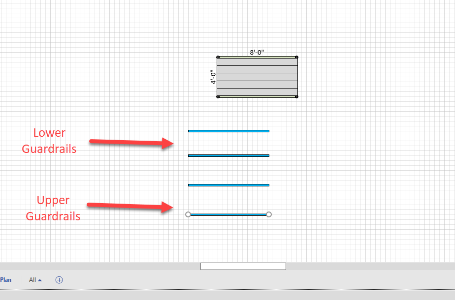
Click and drag the guardrails into place on the bay.
The result looks like this: