Whilst there is no roof object, it is possible to use existing objects (such as a beam) to create a roof truss.
A roof truss can be used as part of a hanging scaffold.
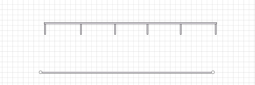
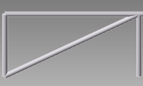
The image below is a roof object, created using beams, on the plan page.
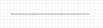
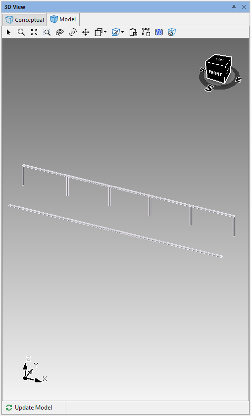
This will then look like this in the 3D view.
Note: Before you begin, it is recommended that you enable the Shape Data dialog.
To create a roof truss.
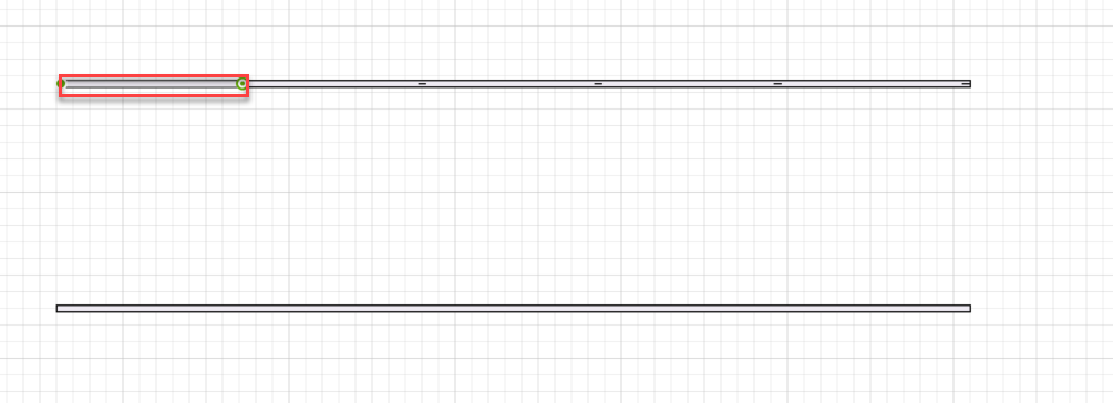
Drag a beam onto the design page.
Click the beam.
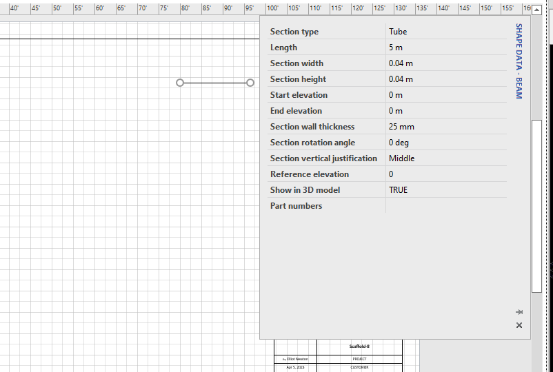
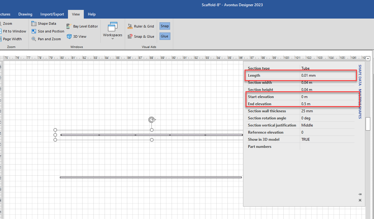
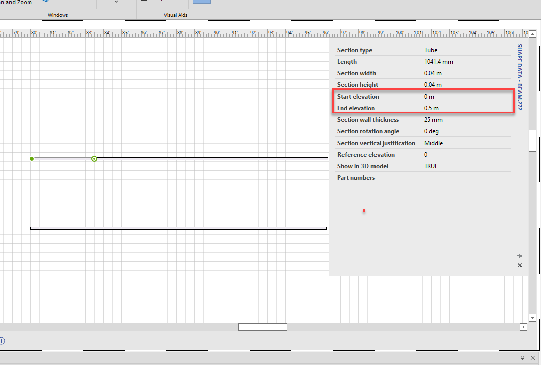
In the Shape Data dialog
Set Section Type to Tube.
Set the Length, Width and Height
Set the Start Elevation and End Elevation. In this example we will set it to 0m.
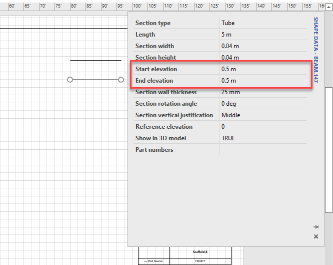
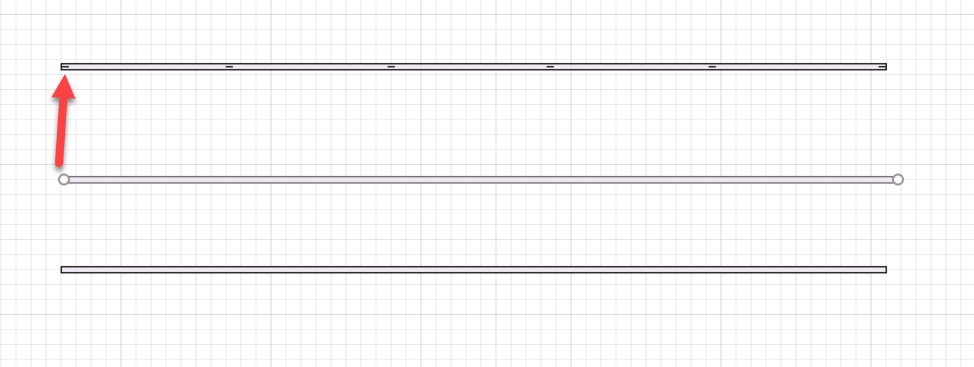
Copy and paste (ctrl + C then Ctrl + V) the beam parallel to the original beam. This beam will act as the lower beam.
In the Shape Data dialog, set the Start and End Elevation to 0.5. This sets the beam to be lower than the original beam.
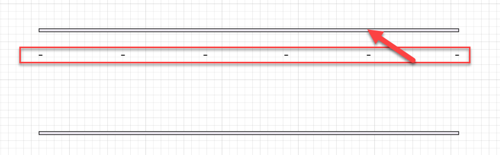
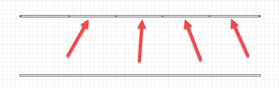
Copy and paste the new beam and adjust the size of the beam to create the vertical lacers, making them small but easy to click on. These lacers will be placed between the upper and lower beam.
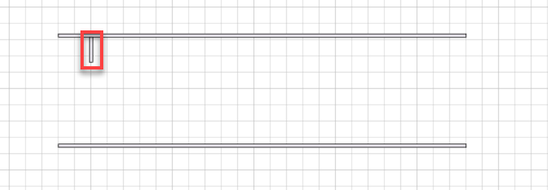
Copy the lacer and place them equally along the beam.
Hold Shift or Ctrl and select each lacer.
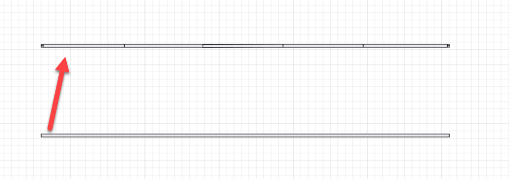
In the Shape Data dialog, set Length to 0.01mm and set both the Start and End Elevation to the desired height. For example, we will set the Start Elevation to 0m and end Elevation to 0.5m. This means the lacer is now vertical and the correct height between the first and second beams.
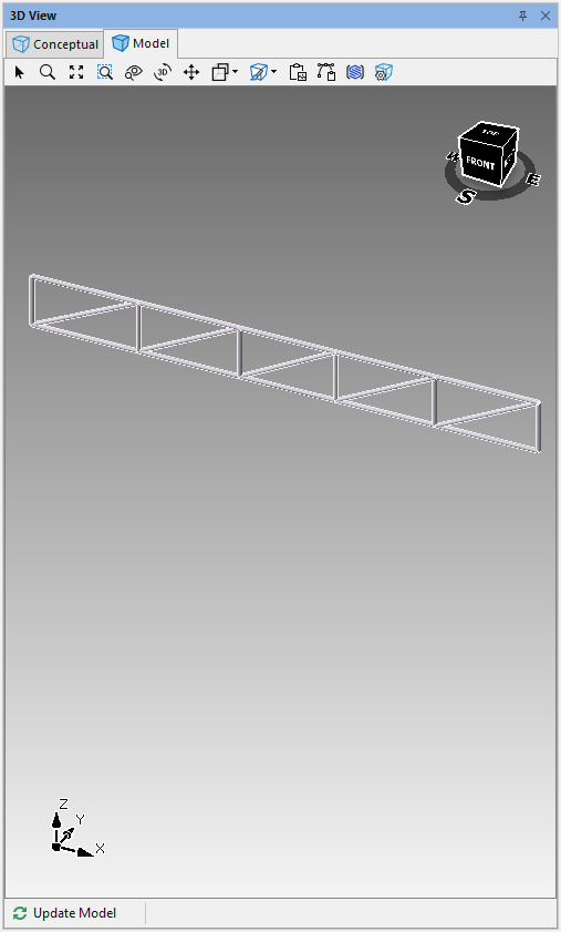
If required, place the lacers on the original beam. This can be done by selecting the lacers and then using the up arrow key on your keyboard.
The 3D panel should look like this.
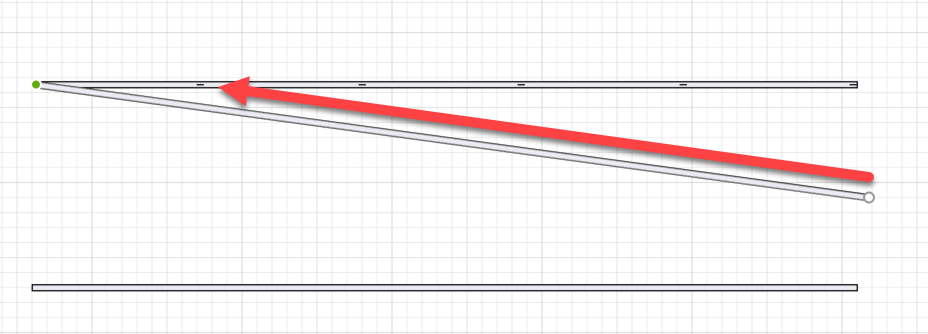
Next we will create diagonal lacers.Copy and paste a new beam. These beams will act as the diagonal lacers.
Select the new beam and drag the end of the beam to a lacer.
Drag the other end to the next lacer.
Click on the beam
In the Shape Data dialog, change the Start and End Elevations to the required elevations to create the diagonal lacer.
The first lacer will look like this:
Copy the beam in between the lacers.
Paste the beam between the remaining lacers.
Move the bottom beam over the top beam so they are on top of each other.
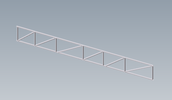
The model will look like this.
Note: You can also change the direction of the diagonal lacers. To do this, swap the Start and End Elevations around so that the Start Elevation is greater than the End Elevation.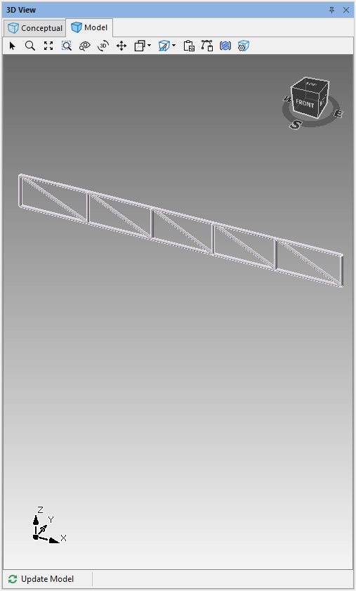
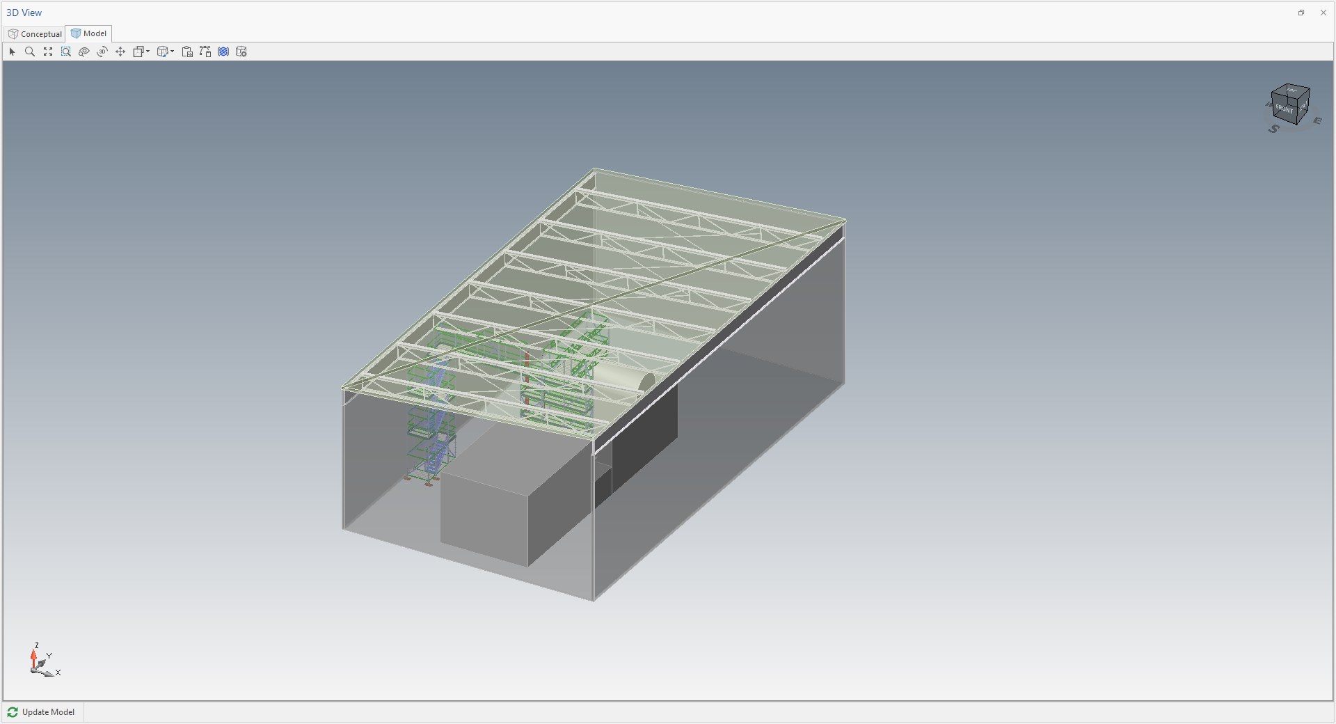
The created roof truss can form part of a major project, such as the one below.