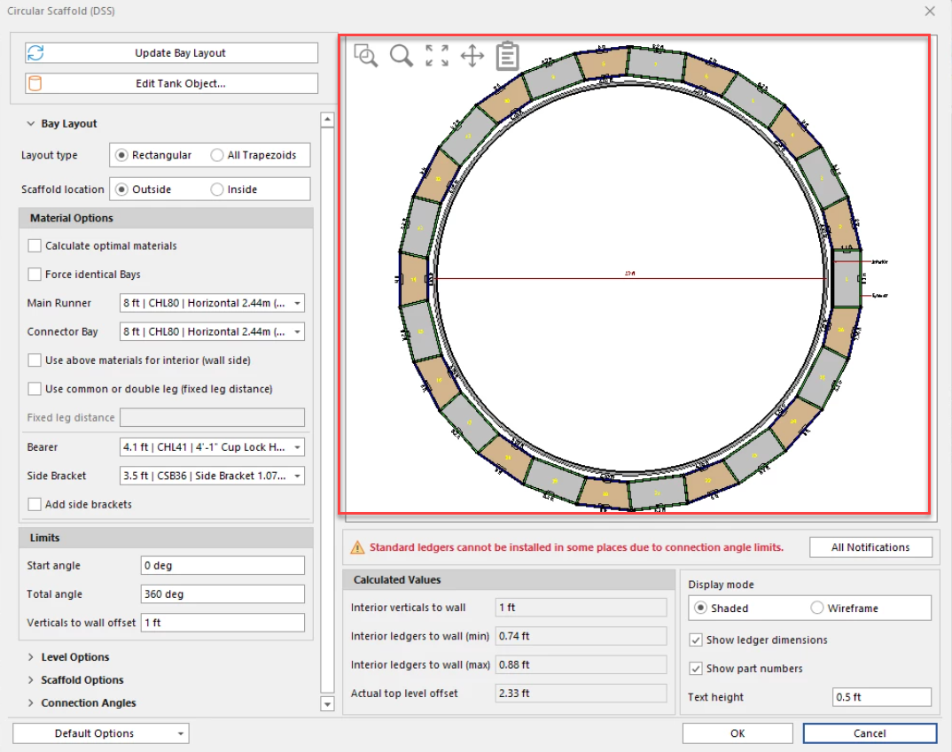
The Circular Scaffold dialog enables you to configure all the details for a full or partial scaffold design for a Tank. The top right area of the dialog, contains the Drawing Area, which displays a drawing of your scaffold design as you create it. You can zoom in to and out of this area and copy the drawing to your computer's clipboard.
The Scaffold Drawing Area
click and drag to form a window to zoom into the area you wish to view
The Scaffold Drawing Area shows a 2D representation of the Tank and the Scaffolding that is currently configured for the Tank. This area has tools for zooming the diagram in and out, moving the diagram around and copying it to your clipboard.
| Click and drag to form a window to zoom into the area you wish to view |
| Use the Zoom tool to zoom in to the diagram. Click the tool, then click on the diagram and drag the Zoom cursor. |
| Use the Pan tool to move the diagram around the Diagram area. Click the tool, then click and drag the Pan cursor. |
| Use the Zoom Fit tool to return the diagram to its default size and location. Click the Zoom Fit tool and click in the diagram area. |
| Use the Copy View to Clipboard tool to copy the Tank and Scaffold diagram to your computer's clipboard. |
Below the Drawing Area
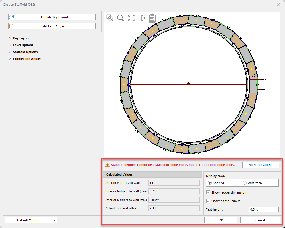
Below the Drawing Area, you will find:
| Interior Verticals to Wall | The Interior Verticals to Wall text field displays the distance that Avontus Designer has calculated that will exist between the walls of the Tank and verticals. |
| Interior Ledgers to Wall (min) | The Interior Ledgers to Wall (min) text field displays the smallest distance that Avontus Designer has calculated that will exist between the walls of the Tank and ledgers. |
| Interior Ledgers to Wall (max) | The Interior Ledgers to Wall (max) text field displays the largest distance that Avontus Designer has calculated that will exist between the walls of the Tank and ledgers. |
| Actual Top Level Offset | The Actual Top Level Offset text field shows you the Top Level Offset as calculated by Avontus Designer (rather than the offset you entered). |
| All Notifications | Displays all errors with the circular scaffold |
| Display Mode | Click the appropriate Display Mode radio button to determine how Avontus Designer displays the scaffold drawing above, as 2D shaded drawing or as a wireframe. |
| Show Ledger Dimensions | Use the Show Ledger Dimensions checkbox to determine whether Avontus Designer displays ledger dimensions in the scaffold drawing above. |
| Show Part Numbers | Use the Show Part Numbers checkbox to determine whether Avontus Designer displays part numbers in the scaffold drawing above. |
| Text Height | Use the Text Height text field to determine the size of the text in the scaffold drawing above. |
The Bay Layout Tab
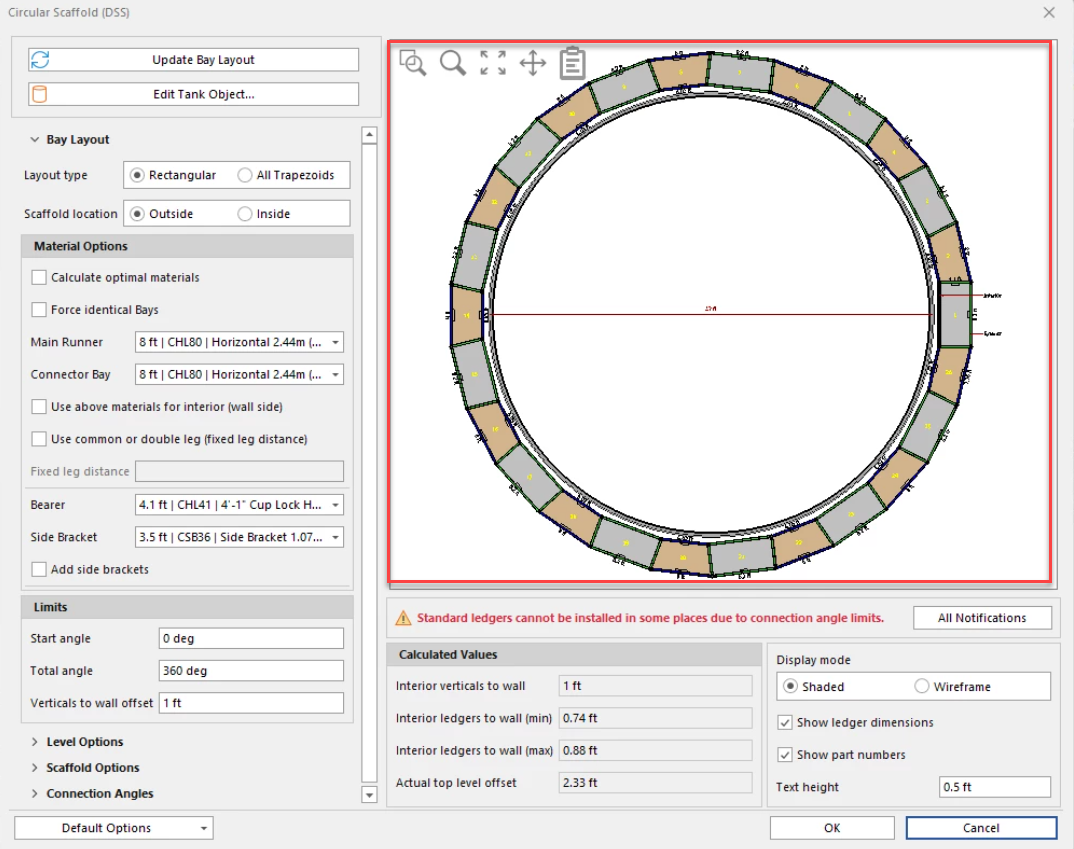
Use the features in the Bay Layout tab to configure Bays for the selected Tank: type of Bay, where located (inside the Tank or outside of it), Bay materials, etc.
| Layout Type | Use the appropriate Layout Type radio button to determine whether Avontus Designer will use rectangular Bays and trapezoidal Bays in the drawing or all trapezoidal Bays. |
| Scaffold Location | Use the appropriate Scaffold Location radio button to determine whether Avontus Designer will draw the Scaffolding inside the Tank or outside of it.. |
| Calculate Optimal Materials | Use the Calculate Optimal Materials checkbox to determine whether Avontus Designer will automatically configure Bays, based on the default Bay dimensions. Part of this calculation is cost-effectiveness and efficiency. |
| Force Identical Bays | Use the Force Identical Bays checkbox to determine whether Avontus Designer will use identical Bays in the drawing. This may affect the distance at which Avontus Designer can place the bays from the outside Tank wall. |
| Main Runner | Use the Main Runner dropdown to determine the length of rectangular based, based on their runner length. |
| Connector Bay | If you click the Rectangular Layout Type radio button, the Connector Bay dropdown becomes active. Use the Connector Bay dropdown to determine the exterior length of Connector Bays. This fixes the exterior length of Connector Bays. |
| Use Above Materials for Interior (Wall Side) | Use the Use Above Materials for Interior (Wall Side) dropdown to determine whether Avontus Designer will use the exterior length of Connector Bays (set above) as the interior length of Connector Bays. This fixes the interior length of Connector Bays. |
| Use Common or Double Leg (Fixed Leg Distance) | Use the Use Common or Double Leg (Fixed Leg Distance) checkbox to determine whether Avontus Designer will use common leg Scaffolding or double leg Scaffolding. When you click the Use Common or Double Leg (Fixed Leg Distance) checkbox, Avontus Designer uses Standard Bays in the scaffold design. This will require the use of corner deck fillers. Therefore, if you click this checkbox, the Use Corner Deck Filler dropdown in the Scaffold Options tab becomes active. |
| Fixed Leg Distance | Use the Fixed Leg Distance text field to determine the Fixed leg distance. If you click the Use Common or Double Leg (Fixed Leg Distance) checkbox, the Fixed Leg Distance text field becomes active. |
| Bearer | Use the Bearer dropdown to select the type of bearers you want to use with the current Tank Scaffolding |
| Side Bracket | Use the Side Bracket dropdown to select the type of side brackets you want to use with the current Tank Scaffolding. |
| Add Side Brackets | Use the Add Side Brackets checkbox to to determine whether Avontus Designer will add side brackets to the Scaffolding Bays. Avontus Designer adds the side brackets to the side of the Bay facing the Tank. |
| Start Angle | Use the Start Angle text field to determine where Avontus Designer will start a partial scaffolding design. Avontus Designer divides Tanks into 360 degrees, with zero (0) being located in the mid right of the Tank (where the diameter line intersects with the Tank wall in the Drawing View area of the Circular Scaffold dialog.). if you enter zero into this text field, this is where Avontus Designer will start building partial scaffolding. |
| Total Angle | Use the Total Angle text field to determine where Avontus Designer will end a partial scaffolding design. Avontus Designer divides Tanks into 360 degrees, with zero (0) being located in the mid right of the Tank (where the diameter line intersects with the Tank wall in the Drawing View area of the Circular Scaffold dialog.).If you enter zero (0) as the Start Angle and 90 as the Total Angle, Avontus Designer will start the partial Scaffolding in the mid right of the Tank and end it at the top of the tank. |
| Verticals to Wall Offset | Use the Verticals to Wall Offset text field to determine the distance between the scaffolding verticals and the Tank walls. |
The Level Options Tab
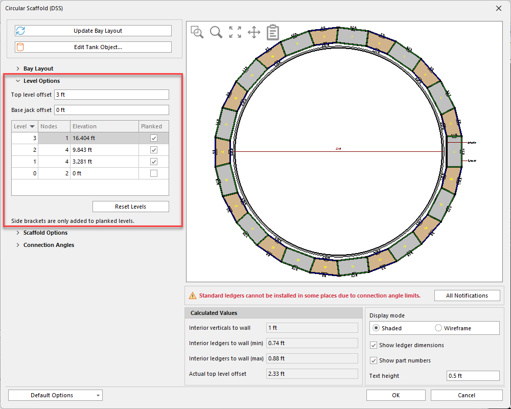
Use the features in the Level Options tab to configure the levels in the Scaffolding around the selected Tank.
Top Level Offset | Use the Top Level Offset text field to determine the vertical distance between the top level deck relative to the top of the Tank. |
| Base Jack Offset | Use the Base Jack Offset text field to determine the vertical distance between the bottom of the jacks to the bottom of the Tank. An entry of zero (0) means the bottom of the jacks are even with the bottom of the Tank |
| Level | The Level columns displays the level numbers in the Scaffold. You cannot edit the cells in this column. |
| Nodes | The Nodes text field displays the number of nodes in each level. You can edit the cells in this column. |
| Elevation | The Elevation column displays the elevation of the bottom of each level. You cannot edit the cells in this column. |
| Decked | The Decked column displays checkboxes that show whether or not each level is decked. You can edit the cells in this column. If a checkbox has a check, that level is decked. |
The Scaffold Options Tab
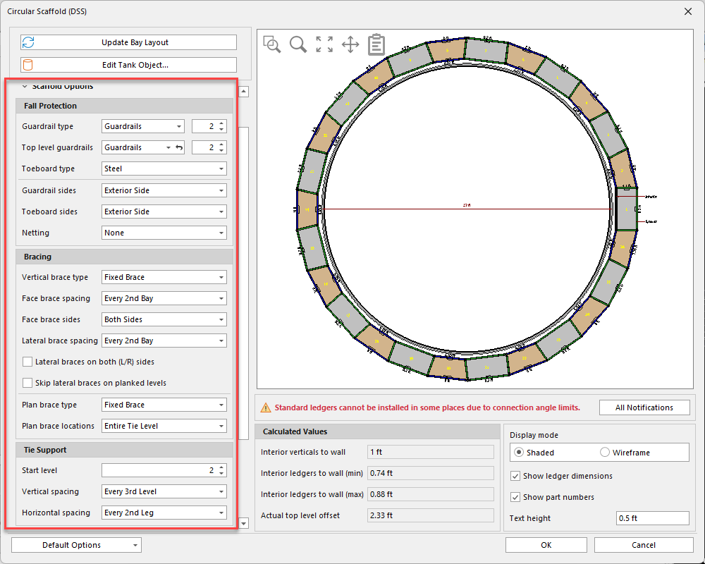
Use the features in the Scaffold Layout tab to configure the scaffolding components for the selected Tank.
| Guardrail Type | Use the Guardrail Type dropdown to determine what type of guardrail Avontus Designer will use on the Scaffolding around the current Tank. Your options are:
Use the field to the right to specify the number of guardrails |
| Top Level Guardrail Type | Use the Guardrail Type dropdown to determine what type of guardrail Avontus Designer will use on the top level of Scaffolding around the current Tank.Your options are:
Use the field to the right to specify the number of top guardrails |
| Toeboard Type | Use the Toeboard Type dropdown to determine what type of toeboards Avontus Designer will use on the Scaffolding around the current Tank. Your options are:
|
| Guardrails Sides | Use the Guardrails dropdown to determine where Avontus Designer will place the guardrails on the Scaffolding around the current Tank. Your options are:
|
| Toeboards Sides | Use the Toeboards dropdown to determine where Avontus Designer will place the toeboards on the Scaffolding around the current Tank. Your options are:
|
| Netting | Use the Netting dropdown to determine where Avontus Designer will place netting on the Scaffolding around the current Tank. Your options are:
|
| Vertical Brace Type | Use the Vertical Brace Type dropdown to determine what type of vertical bracing Avontus Designer will use on the Scaffolding around the current Tank. Your options are:
|
| Face Brace Spacing | Use the Face Brace Spacing dropdown to determine on which Bays Avontus Designer will place face bracing. Your options are:
|
Face Brace Sides | Use the Face Brace Sides dropdown to determine where Avontus Designer will use face bracing on the Scaffolding around the current Tank. Your options are:
|
| Lateral Brace Spacing | Use the Transverse Brace Spacing dropdown to determine on which Bays Avontus Designer will place transverse bracing. Your options are:
|
| Lateral Braces on both (L/R) sides | Select this apply lateral braces to both sides of the Scaffold |
| Skip lateral Braces on Decked Levels | Use the Skip Transverse Braces on Decked Levels checkbox to determine whether Avontus Designer will skip transverse on levels that have decking. |
| Plan Brace Type | Use the Plan Brace Type dropdown to determine the type of brace Avontus Designer will use for transverse braces. Your options are:
|
| Plan Brace Locations | Use the Plan Brace Locations dropdown to determine where Avontus Designer will place transverse braces. Your options are:
|
| Start Level | Use the Start Level text field to determine the level at which Avontus Designer will start placing tie support. |
| Vertical Spacing | Use the Vertical Spacing dropdown to determine on which levels Avontus Designer will place tie support on the Scaffolding around the current Tank. Your options are:
|
| Horizontal Spacing | Use the Horizontal Spacing dropdown to determine one which leg Avontus Designer will place tie support on the Scaffolding around the current Tank. Your options are:
|
| Plank Type | Use the Plank Type dropdown to determine what types of planks Avontus Designer will use on the Scaffolding around the current Tank. Your options are:
|
| Plank on Bracket Bays Only | Use the Plank on Bracket Bays Only text field to determine whether Avontus Designer will only place planks on Bays with brackets. |
| Use Corner Deck Filler | The Use Corner Deck Filler dropdown becomes active when you click the Use Common or Double Leg (fixed leg distance) checkbox in the Bay Layout tab. When you click that option, Avontus Designer uses Standard Bays in the scaffold design. This will require the use of corner deck fillers. Use the Use Corner Deck Filler dropdown to determine the type of corner deck filler you want ot use with the current scaffold design. Your options are:
|
The Connection Angles Tab
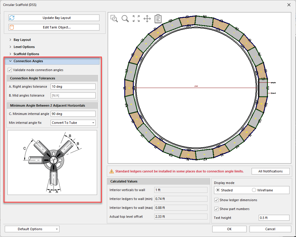
Use the features in the Connection Angles tab to configure angle tolerances and minimums for the Scaffolding for the selected Tank.
| Validate Node Connection Angles | Use the Validate Node Connection Angles checkbox to determine whether Avontus Designer will validate node connection angles. |
| Right Angles Tolerance | Use the Right Angles Tolerance text field to determine how many degrees away from center the members in the larger pin connectors can go. |
| Mid Angles Tolerance | Use the Mid Angles Tolerance text field to determine how many degrees away from 90 the members in the smaller pin connectors can go and still be functional. |
| Minimum Internal Angle | Use the Minimum Internal Angle text field to determine minimum angle allowed between runners in the same pin connector. |
| Min Internal Angle Fix | Use Min Internal Angle Fix dropdown to tell Avontus Designer how you want to handle the connection if the min internal angle is exceeded.
|