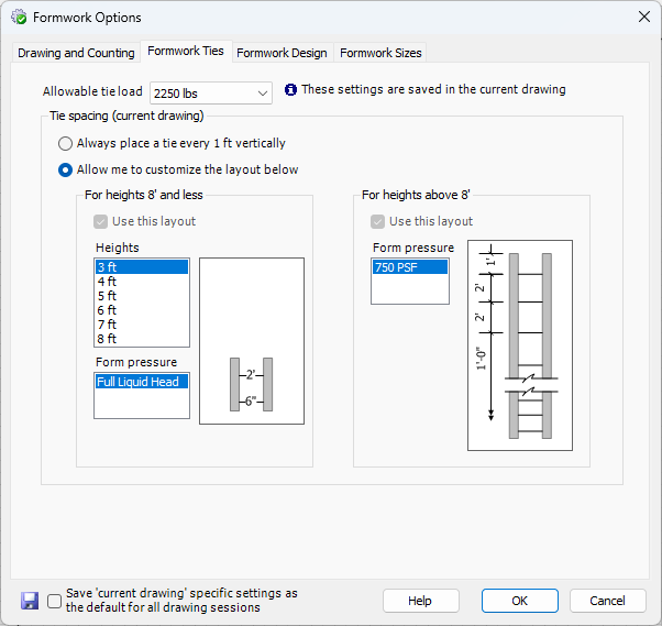
This tab is for formwork ties and allows you to specify formwork ties and tie load.
WARNING! This software is intended for use by qualified formwork designers and competent persons as defined by OSHA. Use by unqualified persons may result in DEATH, SERIOUS PERSONAL INJURY OR PROPERTY DAMAGE. Loading determined by this software is based on the load-carrying capacity of panels, fillers, ties, and other hardware. The total loads on individual components as well as the loading of the formwork assembly must be considered. Bracing and platform design is to be performed by a competent person before proceeding with the work.
Wall Heights
Ties are designed from the Panel heights in the stackup, not the Wall height. For example, if you have specified a custom stackup for a 3-foot Wall to be a 5-foot Panel and draw the Formwork, the tie layout will be for a 5-foot Panel height, not the 3-foot Wall height. This avoids possible failure in the field for cases where a Wall may have accidentally been poured too high, overloading the ties.
Tie Load
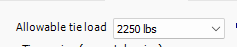
Select the allowable tie load from the dropdown to specify the tie strength you will use for this project. The allowable tie load and Wall height are two major contributors to the tie design that Handset Designer uses (pour rate is also a major contributor and should not exceed maximum values as dictated by Formwork strengths and other conditions). There is a difference between allowable and ultimate tie loading. Handset Designer shows all allowable tie loads. Per code, the allowable tie load has a 2:1 safety factor. Following good practice, Handset Designer uses a single tie load per drawing (which corresponds to a Formwork project) and does not mix heavy and light duty ties.
Tie Placement
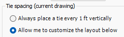
There are two options for the vertical frequency of ties, called tie spacing. First, you can elect to have Handset Designer place ties every 1 ft. on center, regardless of the Panel or tie loading. Second, you can use Tie spacing predetermined for given Wall heights, Tie capacities, and allowable Panel pressures.
Always place a tie every foot
Choosing this option places Ties every 1 ft. on center throughout the Formwork drawings. While this option is selected you are not able to choose from the various Tie patterns for the Wall heights.Allow me to customize the layout
This option enables you to choose from the various heights and Panel pressures to use Ties based on loading.
Two Ranges
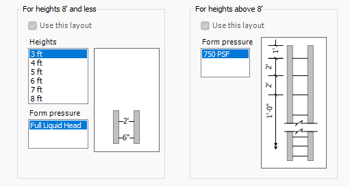
There are two height ranges used to calculate Ties, 8 ft. and less, and heights above 8 ft. If a Wall is exactly 8 ft. high it is used in the layout option for 8 ft. and less.
For both cases, select your Wall height from the lists and then select what Tie layout you want to use by checking the Use this layout checkbox. The Tie layout is only available when there are several form pressure options.
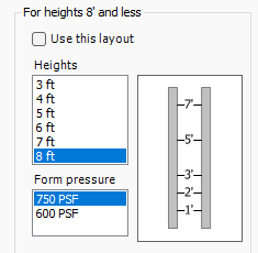
For heights equal to 8 ft. and less, click in the heights in the left listbox to set the Tie locations. The picture to the right of each listbox shows a sample section of the Ties between two sample Panels (which don't represent any actual stackup). The elevations of each Tie are shown in the middle line (the bottom of the Panels is elevation zero).
As you click through the items in both listboxes you'll see the Tie layout displayed that corresponds to this height and pressure. Check the Use this layout checkbox for each layout height you want to use.
Note: You will see different layouts for each allowable Tie load.
As noted in the dialog, after making changes you will most likely need to redraw your Formwork.
![]()