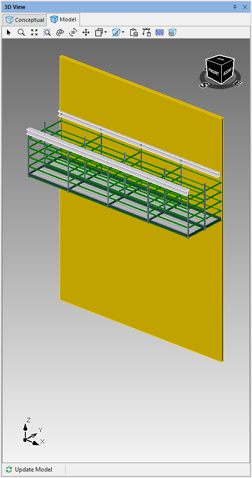
The 3D View panel displays a 3D rendering of the currently active drawing. The panel has two tabs: Conceptual and Model. The Conceptual tab displays a real-time concept of the scaffold design. The Model tab displays an accurate 3D rendering of the Scaffold, including available materials and material substitutions.
When you first click on the 3D Model view, a dialog window will pop up inviting you to share your designs with customers and co-workers using Avontus view. Here, you can download the app for free or view more information by clicking on the relevant links.
This message will appear when you click on the 3D Model view for the first time after starting the software. However, you can hide this pop-up permanently by selecting the Don’t show me this again checkbox.

3D Panel Controls
Use the controls within each tab to adjust the image:
| Pointer | Select individual parts of a drawing. |
| Zoom | Increase or decrease the zoom manually. |
| Zoom Fit | Change the image size to fit the complete image or grid in the window. |
| Zoom Window | Zoom to fit a drawn window area. |
| Magnifier | Magnify specific areas of a drawing. |
| Rotate | Rotate the image on an axis. The axis is determined by where in the image you click. |
| Pan | Move the image within the window. |
| Projection Type | Change the perspective to be parallel with the image. Click again to change back to the previous perspective. |
| Shading Mode* | Select the type of shading you want to appear in the 3D View Panel. Your options are: Realistic, Shaded with Edges, Flat, Hidden Lines and Wireframe. |
| Copy as rasta* | Copy a full-color, 3D image to the clipboard. Some adjustments may occur during this process. |
| Vector Copy* | Copy a simplified, scale-able vector drawing to the clipboard. |
| Export to Avontus Viewer* | Export the current model to Avontus Viewer. |
| Options | Launch the Avontus Designer - Drawing Options dialog. |
| Refresh | Refresh the Model |
| Remove Parts | This button removes the selected part from the 3D view, and removes it from the Bill of Materials. |


* Control only available for Model view.
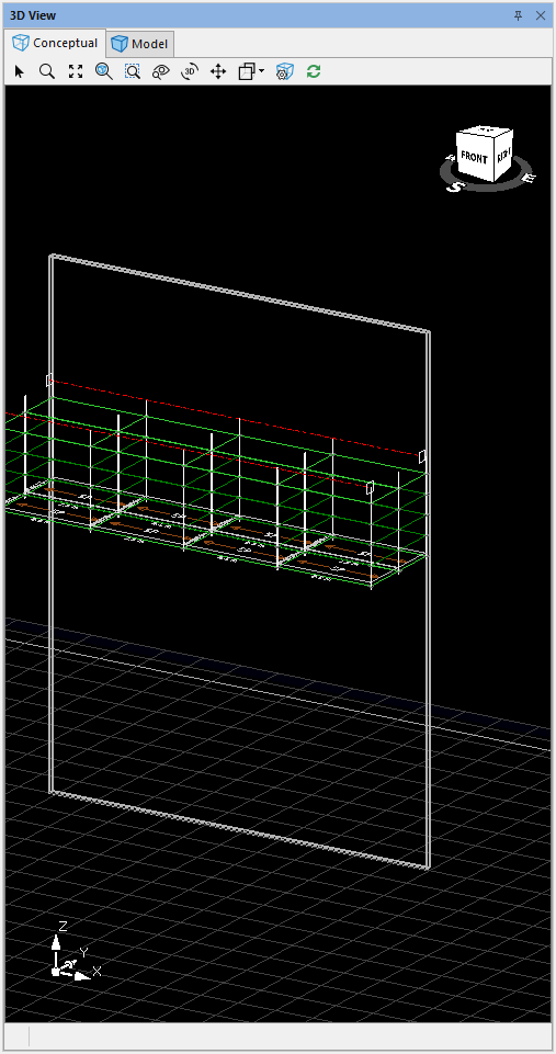
| The View Cube is a useful tool that enables you to adjust an image's pan and rotation at the same time. You can also use it to toggle the perspective to a specific location. Click the desired location on the cube and drag to change the image's orientation. To view the image parallel to a specific side, edge, or corner, click that location on the cube and release. The image automatically adjusts, using the selected location as a center point. Use the compass below the cube to reference the image's orientation to the drawing as designed on the Drawing Page. |
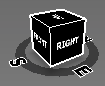
The images below show the Conceptual and Model views, as shown in the 3D View panel for the same scaffold drawing.
Conceptual

Model
Shapes in the 3D View
Select shapes appear in the 3D views, scaled to match the drawing settings and Bay sizes.
Shapes in the Conceptual Tab
Shapes in the Conceptual view appear transparent by default, with just the shape outline visible, despite shape properties for transparency. The outline updates based upon outline or fill properties for the shape.
Shapes in the Model Tab
Shapes in the Model view appear opaque by default. If the shape properties have been updated to include a color fill or transparency, these properties update the shape's appearance in this view. To learn how to make shapes transparent, click here.