You can use a Pilaster as the transition between three Walls that intersect at different angles.To do this, ensure that the Walls are fully contained inside the Pilaster. This procedure shows you how to connect three Walls–two angled and one straight–to a Pilaster.
To create this type of transition:
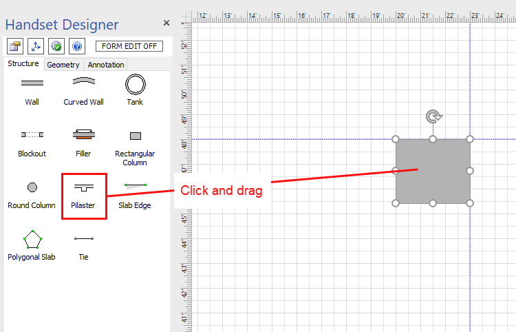
- Click and drag a Pilaster shape onto the Drawing page.
- Click the Size & Position button in the Handset Designer toolbar.
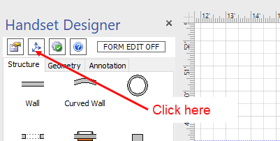
The Size & Position popup appears.
Note: You can also use the Pilaster shape handles to adjust the size of the Pilaster. - As necessary:
- Click in the X text field and enter the X Axis position corresponding to the center point of the Pilaster.
- Click in the Y text field and enter the Y Axis position corresponding to the center point of the Pilaster.
- Click in the Width text field and enter the Pilaster width.
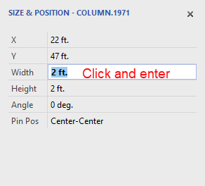
- Click in the Height text field and enter the Pilaster height.
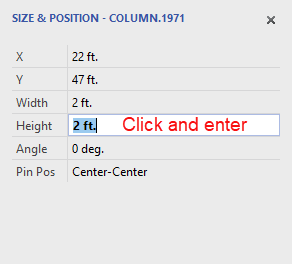
Note: For measurements use ft. for feet, in. for inches and m. for meters. - Click in the Angle text field and enter the angle .
- Click the Pin Position dropdown menu and select the Pilaster pin position.
(For more information refer to Customizing Shape Properties and Setting a Column's Pin Position.)
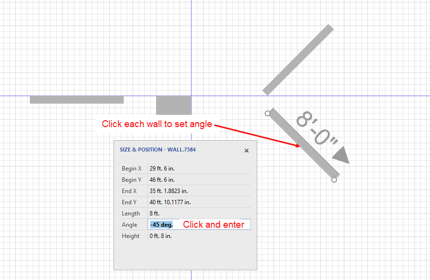
- Click and drag three Wall shapes onto the Drawing page.
- If the Size & Position popup is not already open, click the Size & Position button in the Handset Designer toolbar to open to open it.
- Click one Wall at a time and enter the Wall angle in the Angle text field of the Size & Position popup.
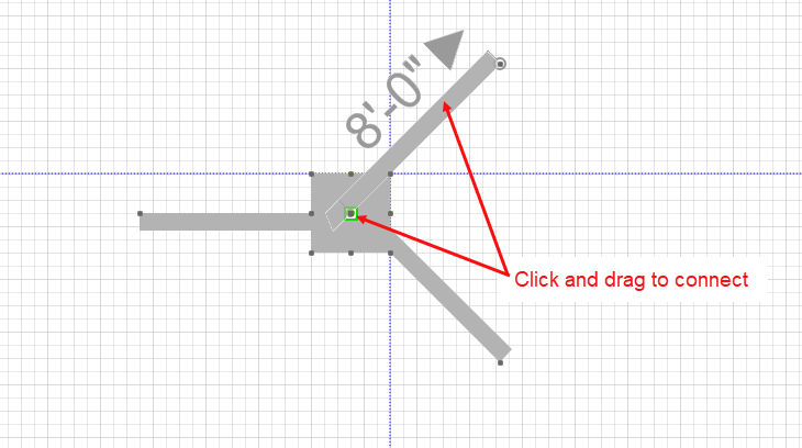
- Click and drag each Wall to a connection point inside the Pilaster.
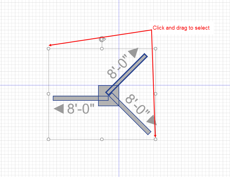
- Click and drag your mouse across the shape to select the Walls and Pilasters as one shape and see the connections.
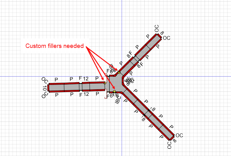
Note: A poorly formed corner will produce Formwork drawing warnings. So it is helpful to draw the Formwork after you have created the Pilaster corner and see if you have created a well-formed connection. (Refer to Formwork Drawing Warnings for more on this subject.) - Click the Handset Designer tab and then click Draw Formwork.
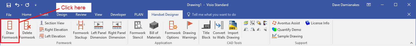
Handset Designer draws the Formwork, revealing no Drawing Warnings. However, since bay corners are fixed angles, it is common that one or more a small custom filler shapes is needed. For these situations you will see a small yellow circle. For more on creating custom Formwork, including fillers, refer to Making and Using Copies of Formwork Parts.