Avontus Designer can calculate the leg loads for a Scaffold. The Leg Loads Table calculates the Dead Load, Live Load, and Total Load for each leg in a scaffold drawing based upon the size, height, location, materials, braces, and other variable factors.
Note: This dialog is meant to be used as a quick reference tool. For more accurate load calculations, consult a certified professional.
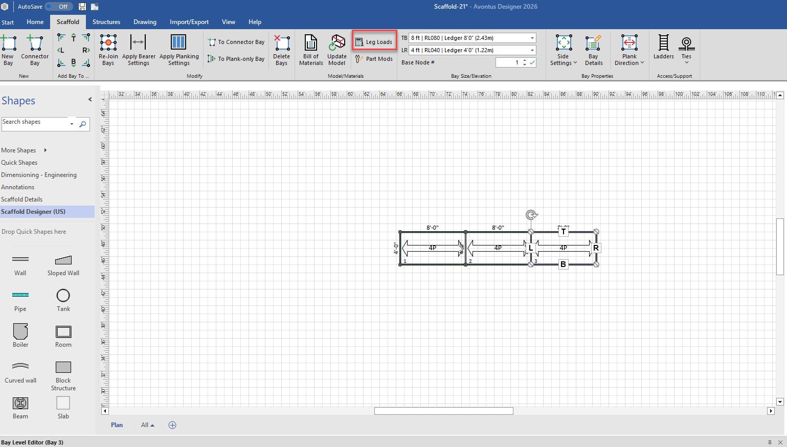
To access the leg load screen, select the Scaffold Tab and click Leg loads.
This will reveal the Leg Loads screen.

Leg Load Calculation Details
Avontus Designer provides general leg load calculations for drawings. For more accurate load calculations, consult a certified professional.
Note: Load calculations are not available for completely suspended scaffolds. Loads for Scaffolds with some suspended Bays may not be transferred.
Total Load (per leg)
Avontus Designer uses the following formula to determine load per leg:
Dead Load + Live Load + Transferred Load = Total Load
Dead Load
Dead Load is the load on the leg by just the Scaffold material. This load does not include the weight of workers, extra materials, or other similar variables. Dead load is calculated using the following formula:
Sum1 + Sum2 = Dead Load
Sum1
This is the weight of all the components directly on each leg that has a screwjack. This includes materials such as vertical posts (standards). screwjacks, headers (if applicable), supported ladder runs, etc.
Sum2
This is 1/4 of the weight all components on the Bays attached to the selected leg's Bay such as planks, horizontals, braces, etc.
Live Load
Live Load is the additional load on the leg when the Scaffold is in use. This includes workers, work materials, etc but does not include the Scaffold materials. Live load is calculated using the following formula:
Usable Deck Area x Unit Live Load = Live Load
Usable Deck Area
This is 1/4 of the area of the Usable Deck levels as defined by the user in the Leg Load Table dialog.
Unit Live Load
This is Unit Live Load as defined by the user in the Leg Load Table dialog.
Transferred Load
Transferred Load is the additional load on the leg for adjacent suspended legs/Bay. Suspended legs are legs without screwjacks. Load will be transferred for up to 1 and 1/2 Bays.
Example of suspended load not transferred
About Suspended Loads
Some suspended leg loads will be transferred to supporting legs. Generally, the load for suspended Bays (Bays without screwjacks) immediately adjacent to a supporting Bay (Bay with screwjacks) are transferred. Load for additional suspended Bays may not be transferred. For details, refer to About Leg Load Calculation Details above.
If the drawing contains a series of suspended legs, in which the load could not be transferred to supporting legs, a warning will appear:
The legs with a suspended load not transferred will be highlighted and shown in italic text. The load for these legs must be manually transferred as desired.
Calculating and Leg Loads for a Drawing
Once you create a Scaffold on the Drawing Page, Avontus Designer automates the calculation of leg loads, based on parameters you define.
To calculate leg loads for a drawing:
Click the Scaffold tab and then click Leg Loads.
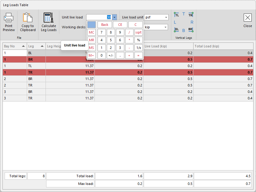
The Leg Loads Table dialog appears.Click in the Unit Live Load text field and enter the appropriate load.
Click in the Number of Usable Deck Levels text field and enter the appropriate number of levels.
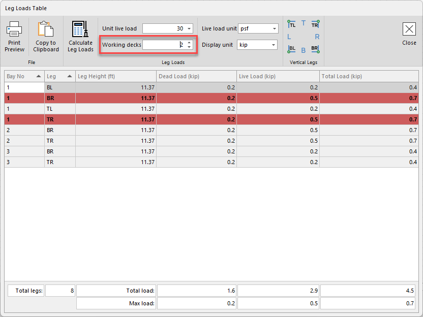
Both values will be used to calculate the Live Load and Total Load.Click Calculate leg Loads
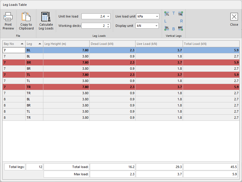
Note: The Leg Loads Table dialog displays a legend in the top-right corner to assist in identifying leg location within a Bay.
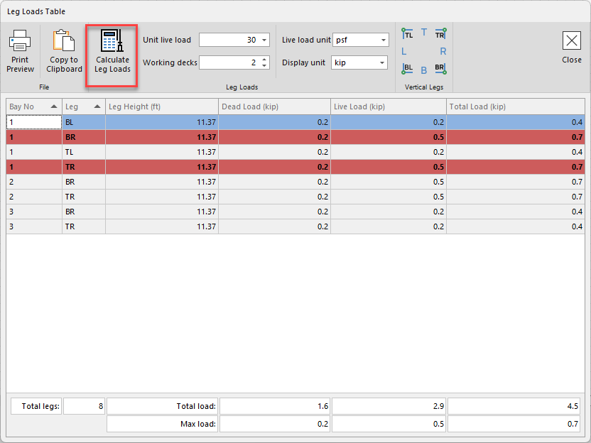
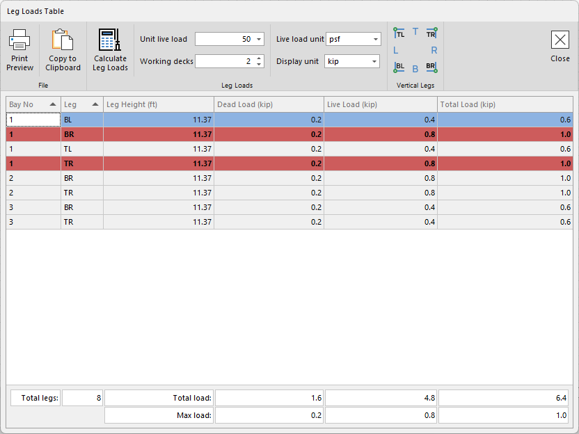
The Leg Load Table displays all legs based upon the drawings specifications.
Note: If legs are shared, the Leg Loads Table dialog only displays them once in the table. The leg with the most load is highlighted in the table.
For information about adding leg load information to a drawing, refer to Copying Leg Loads Table to a Drawing below.
For a detailed calculation information, refer to Leg Loads Calculation Details above.
For information about suspended leg loads, refer to About Suspended Loads above.
Copying the Leg Loads Table to a Drawing
You can add a copy of the Leg Loads Table to any page of a drawing.
To copy the Leg Loads Table to a drawing:
Click the Scaffold tab and then click Leg Loads.
The Leg Loads Table dialog appears.Click in the Unit Live Load text field and enter the appropriate load.
Click in the Number of Usable Deck Levels text field and enter the appropriate number of levels.
Both values will be used to calculate the Live Load and Total Load.Click Calculate leg Loads
Note: The Leg Loads Table dialog displays a legend in the top-right corner to assist in identifying leg location within a Bay.
The Leg Load Table displays all legs based upon the drawing’s specifications. Click Copy to Clipboard.
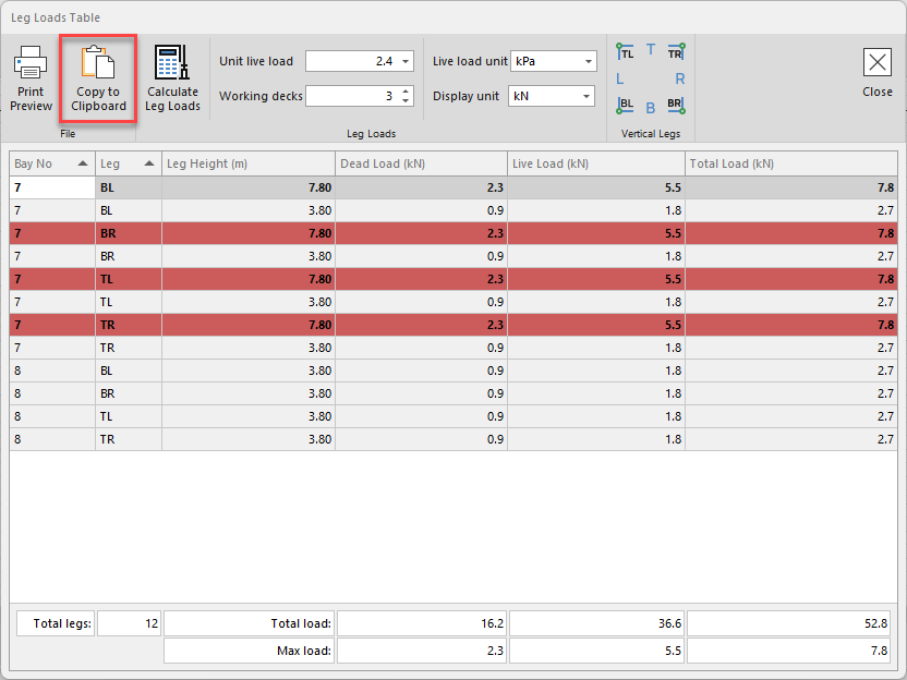
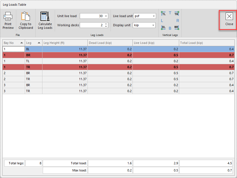
Click Close to return to the Drawing Page.
You can paste the Leg Loads Table to any page of the drawing using standard Windows commands.
Right-click the Drawing Page and select Paste from the menu that appears.
An image of the Leg Loads Table appears in the Drawing Page. You can size this image and move it to the desired location on the page.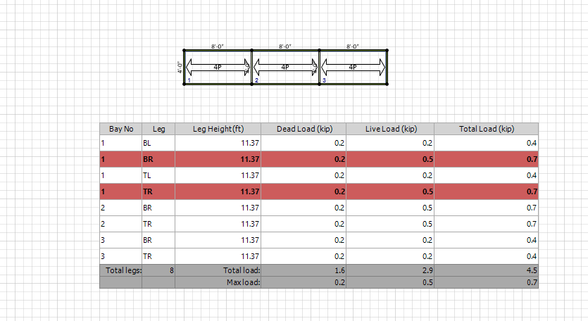
WARNING: If you make changes to the drawing after adding the Leg Loads Table, Avontus Designer will include them in the Leg Load calculations. To include these changes, delete the Leg Loads table image and copy the updated Leg Loads table to the drawing.