Walls are probably the most common component you will use for the structures that you will draw. Because they are such a key element of your drawings, it will be helpful to understand some ways in which Walls behave and some basic ways with which to start working with them.
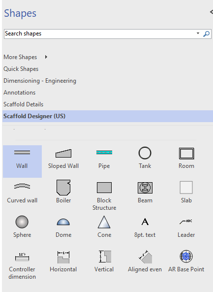
Once your Walls are on the page you can move, stretch or rotate the Walls to arrange them into a building outline. You can also drag and drop Walls onto other Walls and connect them together. This connection is called glue. When you connect one Wall to another, you will see a green box indicating that you are about to glue the Walls together. It is important to make sure each Wall's connection points are aligned when you connect a Wall to another Wall's connection point. Once Walls are connected (glued) to each other, the intersections cleans up automatically.
Your mouse cursor gives you an indicator of what action you are about to perform. If it displays a cross arrow as well as a mouse pointer, you can move the Wall (and unglue it from other Walls if they are connected). If your mouse cursor shows a cross, you can rotate, grow or shrink the Wall.
You can use the Shape Data dialog to control a Wall's length, thickness, height, base elevation, justification, Layer and Color

Note: You can convert a Wall into a Sloped Wall by selecting True from the Sloped Wall dropdown.
Use Visio's Format Shape feature to edit a wall's fill and transparency.
Finally, you can also use the Wall Scaffold feature for automated scaffold design around Walls you create.
This page contains the following:
About Reference Lines
Each Wall has a reference line. This line can be at the top or the bottom of your Wall, depending on your Wall direction. It is visible as a solid dark line that runs across the Wall shape and extends to the edge of your drawing following the direction of the corner handle. Although it is not always obvious (especially when your Walls are connected together), this reference line is the length of the Wall shown in the grey text.
.png "image(29).png")
Below you can see two Walls connected at a right angle. Notice that the reference lines form the outside of the building structure.
.png "image(30).png")
The location of a Wall's reference line determines the default side along which Avontus Designer will create bays when you click Wall Scaffold in the Structures tab.
.png "image(32).png")
About Wall Orientation and Direction
Orientation
Avontus Designer references left and right when referring to one side or another of a Wall. These locations are relative to the direction the Wall is drawn. Once you highlight a Wall and see the direction, left is always the side on which the numerical length and the direction arrow appear.
.png "image(34).png")
Direction
Avontus Designer offers several ways of identifying the orientation of the shapes you draw. Knowing Wall orientation is critical, because the left and right views of a Wall may differ, for example in a sloped floor. Most shapes (Walls, Curved Walls, etc) have start and end points. The direction of a shape can be determined in several ways. For example, when you highlight a wall you will see a numerical length with a grey arrow indicating the direction.
.png "image(39).png")
About Curved Walls
.png "image(40).png")
Curved Walls have all of the controls available with standard Walls, except the Sloped Wall option. They also have an additional control for the radius of the Wall's curve.

Flipping a Wall's Reference Line
Each Wall has a reference line that can be at the top or the bottom (right or left) of a Wall, depending on the Wall's direction. Although it is not always obvious (especially when Walls are connected together), the reference line is the length of the Wall shown in the gray text. You can flip the reference line to reverse the direction.
To flip a Wall's reference line:
1. Right-click the appropriate Wall(s)
2. Select Flip Wall on Reference Line from the menu that appears.
Avontus Designer flips the reference line from the original side to the other side.