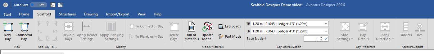
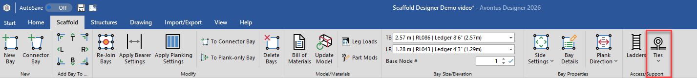
The Scaffold ribbon provides you with the tools to create and customize Scaffolds and Scaffold Bays, ladders, and ties. It also provides access to the Bill of Materials for the active drawing.
New Bay and Connector Bay Controls
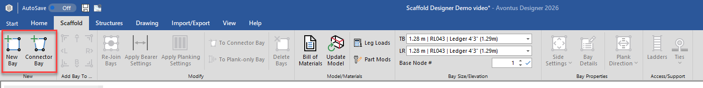
New Bay
Use the New Bay control to add a new Bay to a drawing. To add a Bay, click the New Bay control, drag the new Bay onto the Drawing Page and place it where desired. Once on the page, you can use the Bay Level Editor and other controls to edit this Bay. For more information, refer to Working with Bays.
Connector Bay
Use the Connector Bay control to add a new Connector Bay to a drawing. To add a Connector Bay, click the Connector Bay control, drag the new Connector Bay onto the Drawing Page and place it where desired. Connector Bays are unique in that they can be shaped to connect between two or more at multiple angles. To do this, drag the corners to the desired connection points on the adjoining Bays. For triangular Bays, drag both corners to the same connection point on the adjoining Bay. For more information, refer to Placing a Connector Bay Between Two Standard Bays.
Add Bay to Side Control
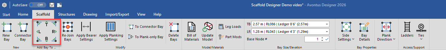
Use the Add Bay to Side control to add a new Bay to any side(s) of any selected Bay. The new Bay will have the same attributes as the selected Bay. To add a Bay to a side, select an existing Bay in the drawing, then click a side or corner location. Please see adding a Connected Bay to a side for more information.
Re-Join Bays Button
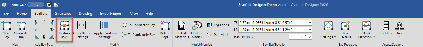
Use the Re-Join Bays to update and recalculate the selected Bay(s). Use this button to ensure that any Bays you add to a drawing share legs with existing Bays, that guardrails do not block the deck path, and any other necessary adjustments. To re-join Bays, you can use standard Windows commands to select multiple Bays. Click an area of the Drawing Page and drag to highlight an area. This selects all the Bays within that area. Click Re-Join Bays when ready.
Note: The Re-Join Bays function does not move the selected Bays, but re-calculates the flow between the selected Bays to ensure consistency.
Apply Bearer Settings
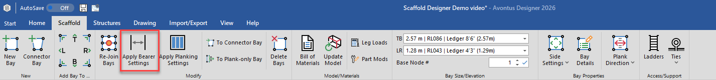
Select to apply the bearer settings, specified in Drawing or Global Options, to the selected scaffolds. Please see Setting Scaffold Bay Global Options for more information.
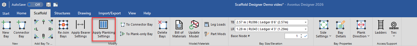
Apply Planking Settings
Apply Planking Settings set in the Global Settings or Drawing Options to the selected Bay.
For more information, please see Setting Scaffold Bay Global Options
To Connector Bay
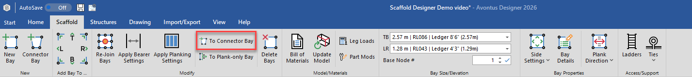
Use the To Connector Bay control to convert the selected Bay to a Connector Bay.
To Plank-Only Bay
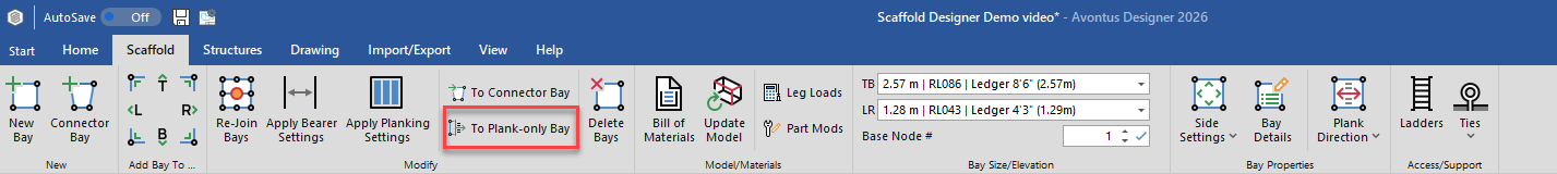
Use the To Plank-only Bay control to convert the selected Bay to a plank-only Bay.
Delete Bays Button
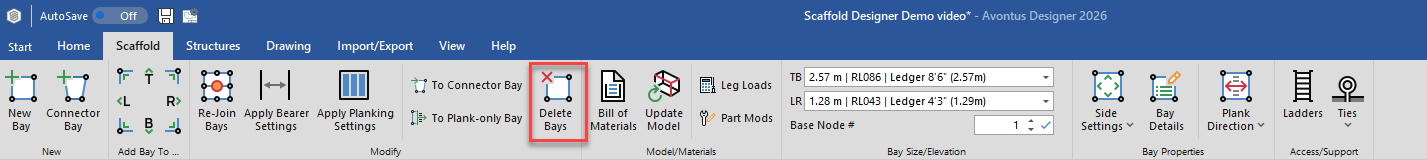
Use the Delete Bays control to delete the selected Bay(s). To delete one or more Bays, you can use standard Windows commands to select multiple Bays. Click in the Drawing Page and drag to highlight an area. This selects all Bays within that area. Click Delete Bays when ready.
Bill of Materials Button
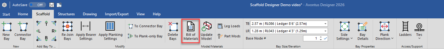
Use the Bill of Materials control to create a Bill of Materials for the currently active scaffold drawing.
The Bill of Materials calculates and displays a list of materials required to build a Scaffold as drawn. This includes the quantity of parts, total weight/volume and netting area that appears in the drawing’s selected unit of measure.
For more information, please see Bill of Materials
Update Model Button
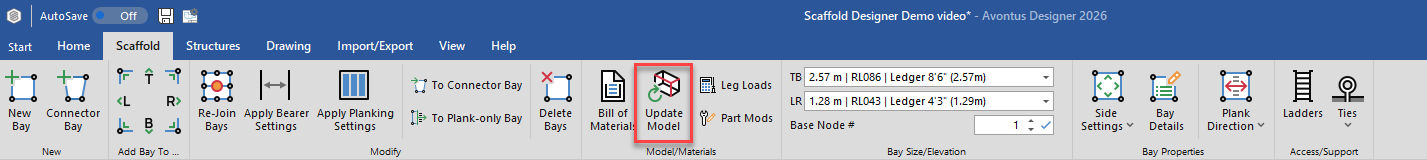
Use the Update Model button to update the 3D Model View of a drawing. Some changes to a drawing (such as adding smartshapes) require an update to include these changes in the model view. To update the 3D Model View, make any desired changes to the drawing then click Update Model.
Leg Loads Button
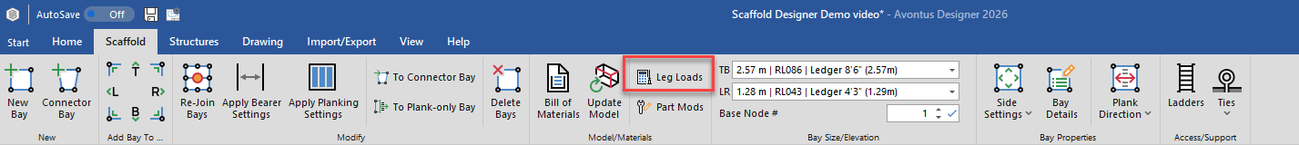
Use the Leg Loads control to calculate the leg loads for a Scaffold. For more information, refer to Working with Leg Loads.
Part Mods Button
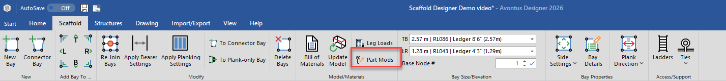
Avontus Designer creates structures in an automatic manner. For example, while Avontus Designer allows you to make some adjustments to the design of each ladder in a Ladder Bay (alternation points, whether the ladder is vertical or angled, etc), you may want to build a Ladder Bay in a way that Avontus Designer may not accommodate very well. For example, you always use bridging beams on an external ladder. Part Modifications enables you to configure Avontus Designer so that whenever you use the external ladder feature, it will add a bridging beam to the Bill of Materials. The beam will not show up visually in Avontus Designer, but it will be on the Bill of Materials. Avontus Designer enables you to create, manage and import/export part modifications.
Bay Side Dropdowns and Elevation Text Field
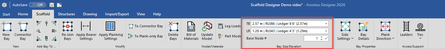
The side of each Bay you add to the Drawing Page are labelled: T, B, L, R. The Bay Side dropdowns enable you to determine the size of selected Bays and the materials with which they are made. The materials available depend on the type of Scaffolding you are using and what is available in the Material Master. The Elevation (Base #) text field enables you to determine the height (relative to ground level) at which selected Bays start.
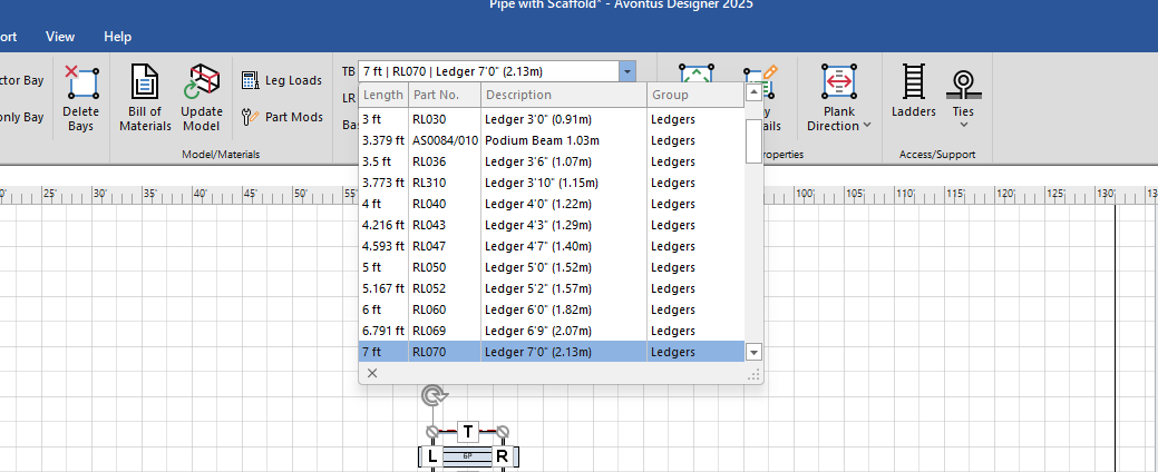
TB
Use the TB control to set the length of selected Bay(s). The length is the distance between the top and bottom ledgers of a Bay. To set the length of Bays, use standard Windows commands to select multiple Bays. Click in the Drawing Page and drag to highlight an area. This selects all Bays within that area. Choose the desired width and materials for the Bays.
LR
Use the LR control to set the width of selected Bay(s). The width is the distance between the left and right ledgers of a Bay. To set the width of Bays, use standard Windows commands to select multiple Bays. Click in the Drawing Page and drag to highlight an area. This selects all Bays within that area. Choose the desired height and materials for the Bays when ready.
Base Node #
Use the Base Node # control to change the starting elevation of selected Bay(s). Each increment increases or decreases the elevation by 0.5 meters (1.64 feet). To change the elevation of Bays, use standard Windows commands to select multiple Bays. Click in the Drawing Page and drag to highlight an area. This selects all Bays within that area. Choose the desired start node for the Bays and click Apply ( ) when ready.
For more information, refer to Working with Bays.
Side Settings Dropdown
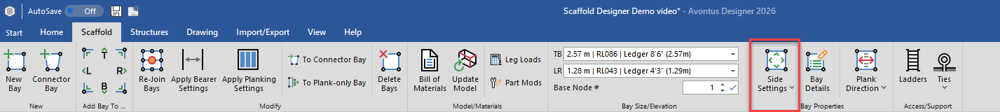
The Side Settings feature located in the Bay Properties control enables you to edit settings for a single Bay or for multiple Bays at once. Changes made with this control will affect every level of the selected Bay(s). For information about editing individual levels of a Bay, refer to Editing Bays using Side Settings.
Bay Details
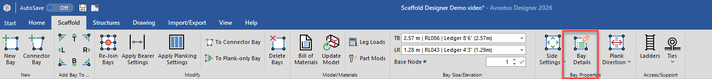
The Bay Details feature allows you to modify the details of the Bay, including the option to skip sides, set the Guardrail type and adjust the elevation of the Bay. For more information, visit the Bay Level Editor.
Plank Direction Dropdown
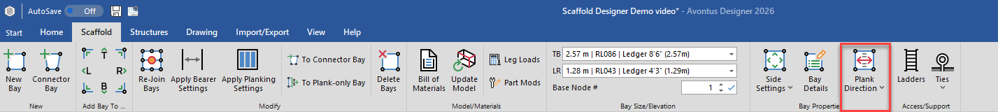
Use the Plank Direction control to change the direction of the planks for selected Bay(s). Planks can be  Parallel or
  Perpendicular in direction. To change the direction of planks within Bays, use standard Windows commands to select multiple Bays. Click in the Drawing Page and drag to highlight an area. This selects all Bays within that area. Click Plank Direction to change all planks to match direction or choose the desired direction from the drop-down options.
For more, information please visit Changing a Plank's direction.
Ladders Button
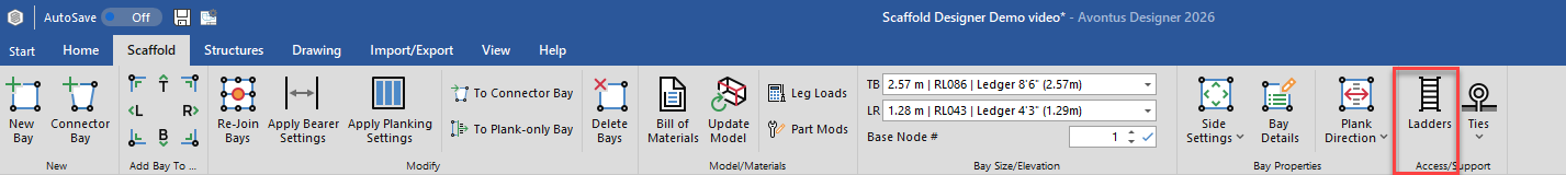
The Ladders control enables you to add ladders to a selected Bay. When you click this control, the Scaffold Ladders dialog appears. Use it to configure ladders for the Bay. For more information, refer to Working with Ladders.
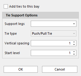
Ties Dropdown
Use the Ties control to add ties to the selected Bay. To add ties, select a Bay within the drawing and click Ties. Select the desired Tie Options and click OK when ready. For more information, please visit Working with Ties.