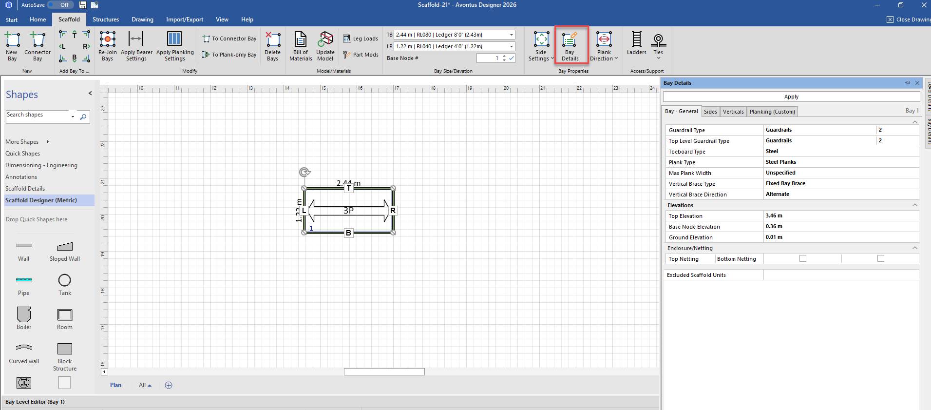
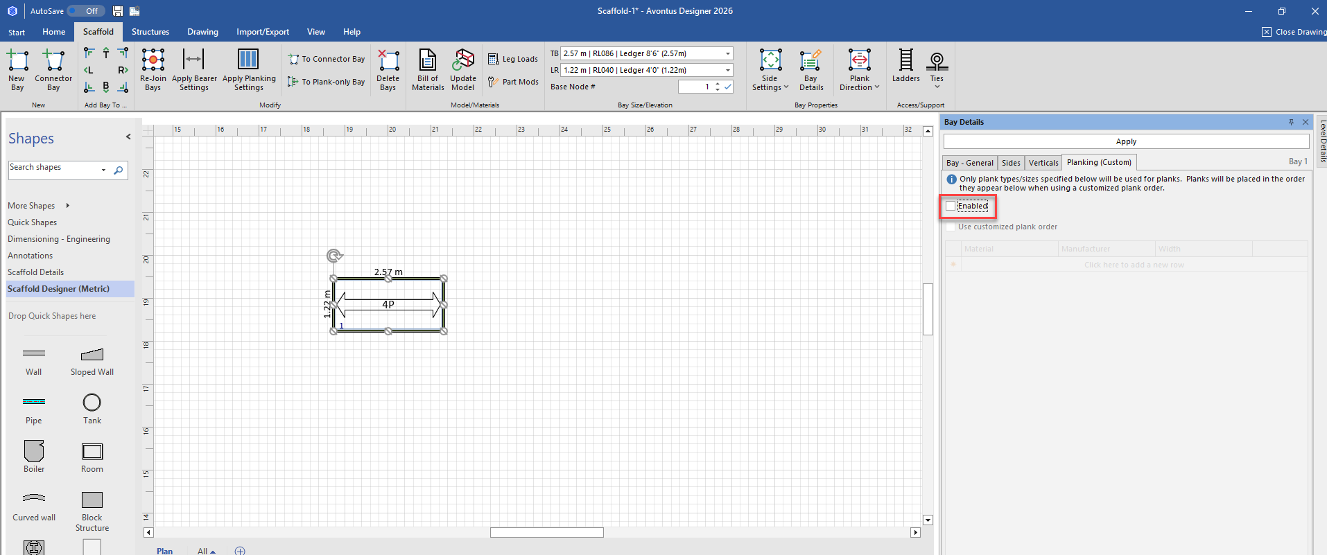
Clicking the Bay Details control (located in the Bay Properties group) launches a dialog with three tabs that provide many options for editing materials and settings for the selected Bay. Avontus Designer applies the options and changes you set through this control to every level of the selected Bay.
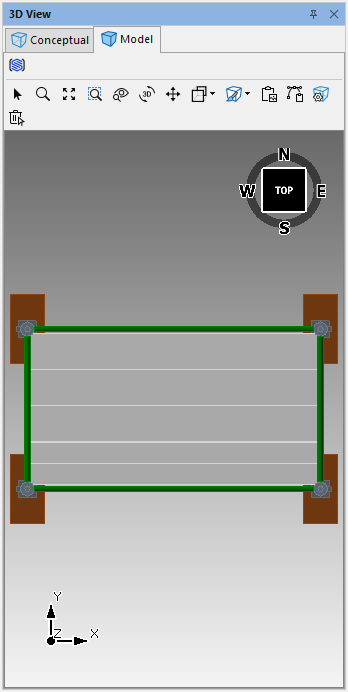
Like any other dialog, you can move the Bay Details dialog anywhere on your desktop that works best for you. You can also dock the Bay Details dialog. This can be especially useful when using a dual monitor setup, with the 3D View dialog on the second monitor.
Note: The Bay Details control is only available when an individual Bay is selected on the Drawing Page. If multiple Bays are selected, this control is disabled.
General Tab
The General tab of the Bay Details control provides material options and settings for the entire selected Bay. Avontus Designer applies the changes made here to every level and every side of the selected Bay, where applicable.
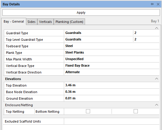
Basic Bay Options
Guardrail Type | Select from the available options to default the guardrail configuration for the Bay. Options include:
Use the numbered selection box to specify how many Guardrails you want added to this level. The maximum is 4. |
Top Level Guardrail Type | Select the top level guardrail type and the number of the guardrails - this will be the guardails on the very top level.
Use the numbered selection box to specify how many Guardrails you want added to this level. The maximum is 4. |
Toeboard Type | Select from the available toeboard materials. Options include:
|
Plank Type | Use the Plank Type dropdown to determine the default plank (deck) materials. Options include:
|
Vertical Brace Type | Select the Vertical Brace Type. Select from: Fixed Bay Brace Tube and Clamp |
Vertical Brace Direction | Use this option to change the brace direction for the selected Bay. |
Top Elevation | Use this option to set the height above the ground at which the top of the scaffold rests. The ground is zero (0). |
Ground Elevation | Use this option to set the height at which the bottom of the scaffold rests. The ground is zero (0). |
Base Node Elevation | Use this option to set the starting height of the base (first) node of the Bay. This should include allowances for Base Collar and Screwjack materials. |
Top Enclosure/Netting | Use this option to add netting to the top of the top node of the selected Bay. |
Bottom Enclosure/Netting | Use this option to add netting to the bottom of the bottom node of the selected Bay. |
Excluded Scaffold Units | Use this option to select one or more scaffold units to exclude them from the Bill of Materials. |
Note: You can edit the General tab on multiple scaffolds at once.
Sides Tab
The Sides tab of the Bay Details control provides side-by-side material settings and options for a selected Bay. The settings and changes you make here will affect every level of the selected Bay, where applicable.
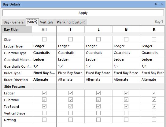
Skip Side | Enable this option to skip materials for this entire side such as Ledgers, Guardrails, and Toeboards. Materials will not be included in the Bill of Materials or 3D Views. Materials shared by more than one side will not be removed. Original settings will be retained in case the option is later disabled. |
Ledger Type | Use the Ledger Type dropdown to determine the ledger material for the selected Bay. Your options include:
|
Guardrail Type | Use the Guardrail Type dropdown to determine the default guardrail configuration for the Bay. Your options include:
|
Guardrail Material | Select from the available options to set the guardrail material for the selected Bay. Use the Guardrail Material dropdown to determine the guardrail material for the selected Bay. Your options include:
|
Guardrail Config | Select how many guardrails will be on that side of the bay, and which ones to skip. If skipped, materials will not be included in the Bill of Materials or 3D Views. Materials shared by more than one side will not be removed. On a 4 node level, 1 represents the guardrail connected to the lowest node and so on. |
Brace Type | Use the Brace Type dropdown to determine the brace materials. Your options include:
|
Brace Direction | Use this option to change the brace direction for the selected Bay. |
Side Settings
This section provides quick access to common side settings. Enable or disable the options to add or remove materials to the selected Bayside. Options include:
Ledger
Guardrail
Toeboard
Vertical Brace
Netting
Verticals Tab
The Verticals tab of the Bay Details control provides options for editing each vertical (leg/standard) of a selected Bay.
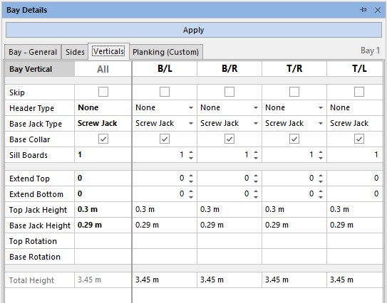
Skip | Enable this option to skip the vertical. The vertical will not be included in the Bill of Materials or 3D Views. Materials shared by more than one Bay will not be removed. Avontus Designer will retain other Bay materials, such as ledgers. |
Header Type | Select the desired type from the available options. Options include:
|
Base Type Jack | Select the desired type from the available options. Options include:
|
Base Collar | Defaults as selected. Indicate if this vertical uses a Base Collar. |
Sill Boards | Defaults to 1. Enter the desired number of sill boards. To remove sill boards, enter 0. |
Extend Options
By default, all verticals for a Bay will be the same length. These options enable you to modify the length of each vertical independently.
Extend Top | This option increases the length of the vertical by adding nodes to the top of the vertical. Enter a positive value to a maximum of 10. Each increment of one represents one node in length. |
Extend Bottom | This option increases the length of the vertical by adding nodes to the bottom of the vertical. Enter a negative value to a maximum of -10. Each increment of one represents one node in length. |
Top Jack Height | Enter the desired height for the top screw jacks. Defaults to 12 in. or 30.48 cm. for flat elevations. |
Base Jack Height | Enter the desired height for the base screw jacks. Defaults to 12 in. or 30.48 cm. for flat elevations. |
Top Rotation | Enter the desired amount (in degrees) in which you want to rotate the screw jacks on the top verticals. |
Base Rotation | Enter the desired amount (in degrees) in which you want to rotate the base screw jacks. |
Total Height | These read-only text fields display the total length of each vertical, including all standards, headers, base, base collar, and any extensions (excluding sill boards) |
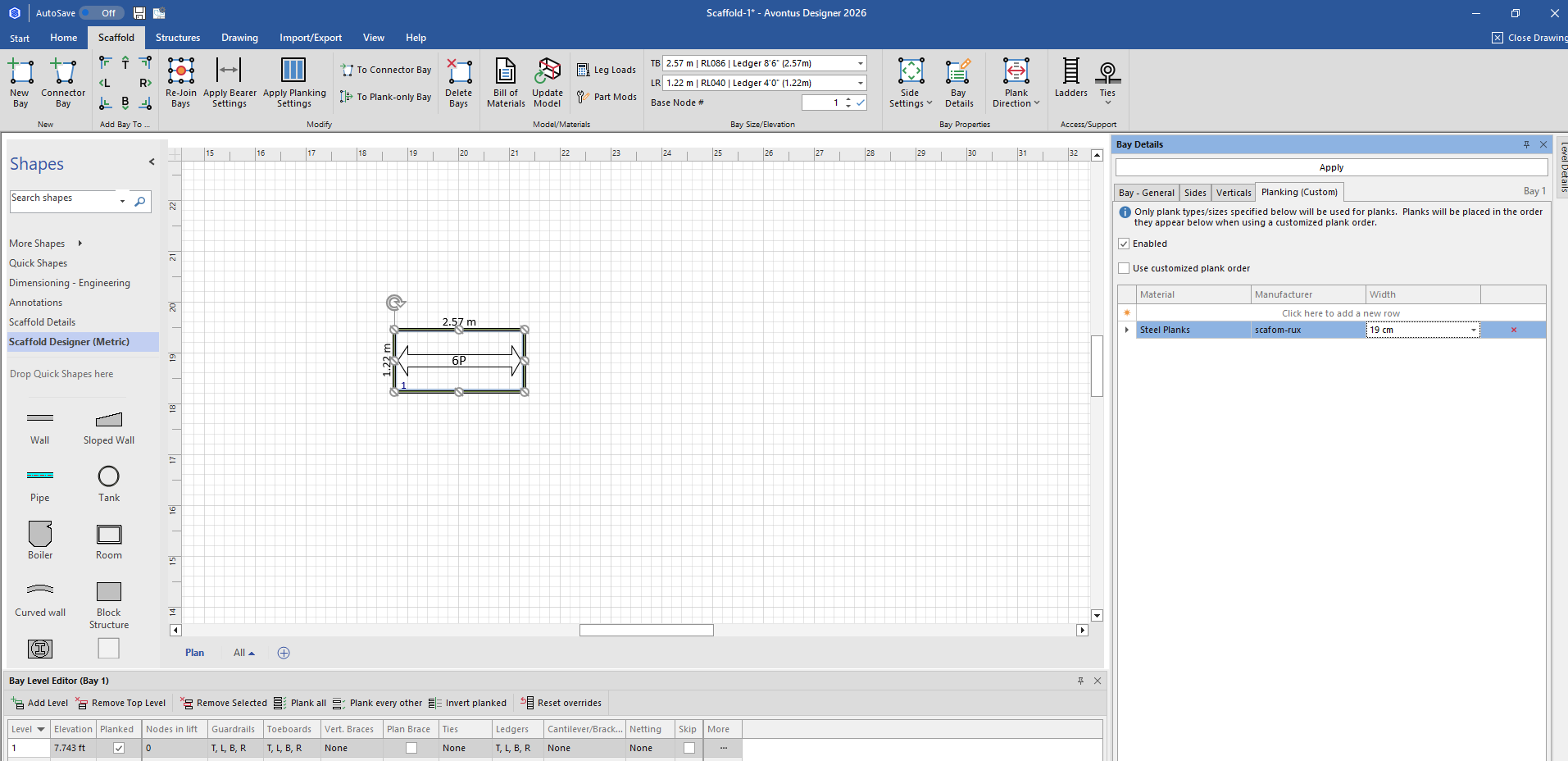
Planking (Custom)
This tab allows users to apply custom planking to bays. Only plank type/sizes specified will be used to planks. For example, you can use planks from a specific manufacturer, at a specfic size. Planks will be placed in the order they appear when using a customised plank order
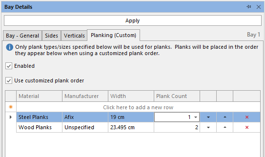
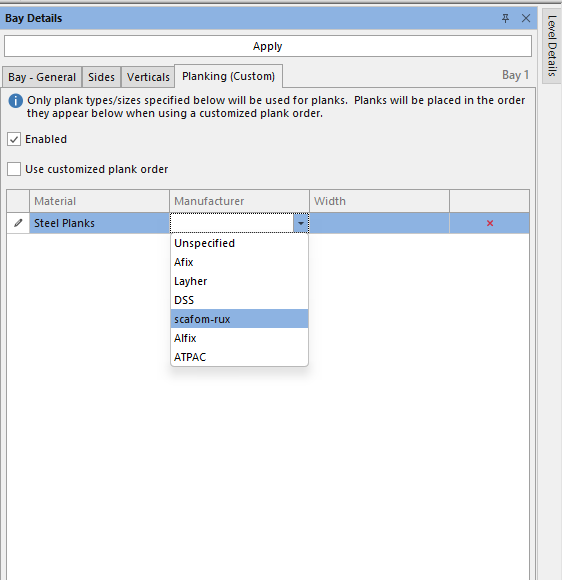
First, select the Bay, and in the Planking tab for the Bay Details, click the Enabled check box.
Click the Material drop-down, and select the material type.
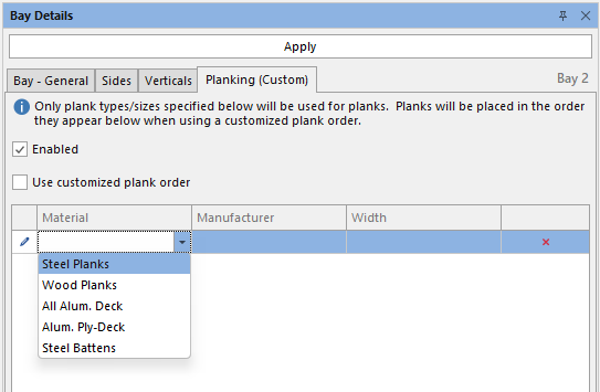
Then complete the Manufacturer and Width columns.
Click Apply. In the image below the plank custom options specified will be applied to the Bay. The number of planks may change.
You can also customise the planking order, where you can specify that the bay uses more than one type of plank, such as different size planks.
Click the Use Customised plank order checkbox, and specify the custom plank options.
In the example below, we are using 2 Afix planks of 19cm and three Afix planks of 32cm.
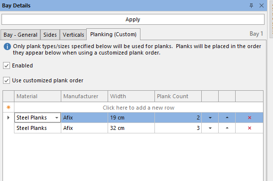
The Bay will now have 5 planks.