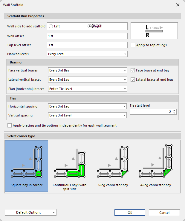
The Wall Scaffold feature automates the layout of Scaffolding based upon the dimensions and elevations of selected walls. When you select the walls around which you want to add Scaffolding and click Wall Scaffold, the Wall Scaffold dialog appears. Use it to determine the most common bay options for the design. After you click OK, Avontus Designer builds the Scaffolding. You can use features like Bay Details, Side Settings and the Bay Level to fully customize every bay.
You will find the following on this page:
Scaffold Run Properties Section | |
Wall Side | This is the side of the wall(s) along which the Scaffold will be drawn. A legend is provided to help determine the direction of a wall. Wall directions are indicated by a directional arrow on each wall, visible when the wall is selected on the Drawing Page. |
Wall Offset | This is the minimum distance that will be maintained between the Scaffold and the walls. |
Top Level offset | This is the approximate distance from the top of the wall to which the top level of the Scaffold should reach. A negative value in this field sets the top level of the Scaffold below the top of the wall. A positive value in this field extends the top level of the Scaffold above the top of the wall. This applies to the start of the top level and does not include additional height for guardrails, etc. |
Apply to Top of Leg | If the Scaffold standards/verticals should not extend above a certain height (perhaps due to a roof or overhead obstruction), select this option and the value you enter will apply to top of the standards/verticals instead of the top level of the Scaffold. |
Planked Levels | Select from the available options to default the planked levels for the scaffold design. Your options are:
|
Bracing Section | |
| Face Vertical Braces | Use the Face Vertical Braces dropdown to determine where Avontus Designer will place longitudinal vertical braces. Your options are:
|
| Face Brace at end of Bay | Click this to apply a Face Brace the end of the bay |
| Lateral Vertical Braces | Use the Transverse Vertical Braces dropdown to determine where Avontus Designer will place transverse vertical braces. Your options are:
|
| Lateral Brace at end legs | Click this to apply a lateral brace at the end of the scaffold bay's legs. |
| Plan (Horizontal) Braces | Use the Plan (Horizontal) Braces dropdown to determine where Avontus Designer will place plan braces. Avontus Designer places these braces at a diagonal when viewing the Scaffold Bay from the top, or plan view. Your options are:
|
Ties Section | |
| Horizontal Spacing | Use the Horizontal Spacing dropdown to determine the tie leg locations for the scaffold design. Your options are:
|
| Vertical Spacing | Use the Vertical Spacing dropdown to determine the tie levels for the scaffold design. Your options are:
|
| Tie Stat Level | Select which Level the ties start |
| Apply Brancing and tie options independently for each wall segment | Select this so each wall segment is unaffected bt the bracing and ties before it. If enabled, Ties and Bracing will start on the selected leg or levels. |
Select Corner Type Section | |
| Select Corner Tpye | Corner type options vary based upon the selected Scaffold System for the drawing. For more information, refer to CornerTypes below. |
Bottom Section | |
Restore Default Settings | Click Restore Default Settings to restore Avontus Designer default settings for the Wall Scaffold feature. |
Save Current Settings as Default | Use the Save Current Settings as Default checkbox if you want Avontus Designer to use the currently entered values and selected options as the default settings each time the Wall Scaffold feature is launched for a new layout. |
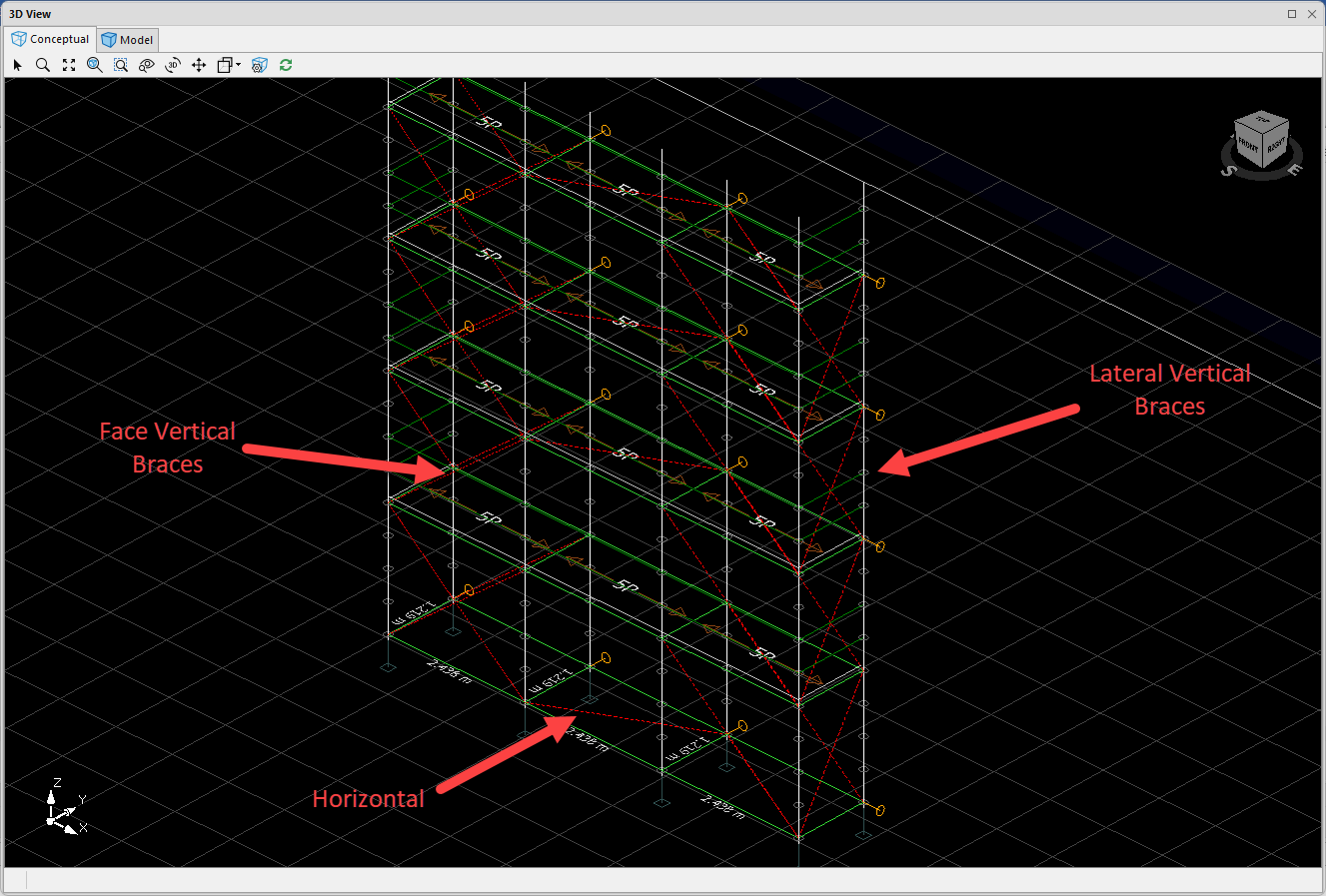
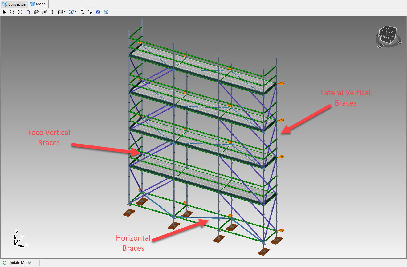
Bracing
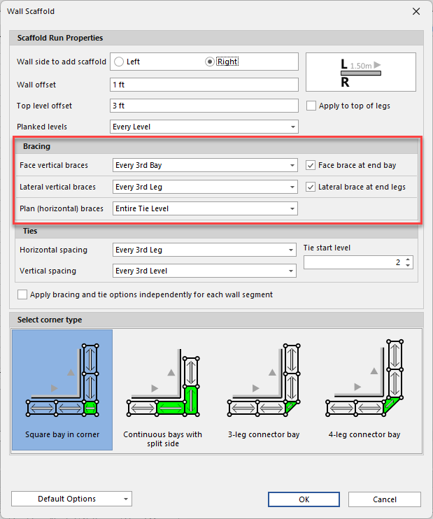
The Wall Scaffold feature provides various bracing options. Braces are depicted as dashed red lines in the drawing page and are rendered in the 3D Wireframe and Model views.
Corner Types
The Wall Scaffold structure provides various corner types, based upon the Scaffold Material you select for the drawing.
Ring and Cup Type Scaffold
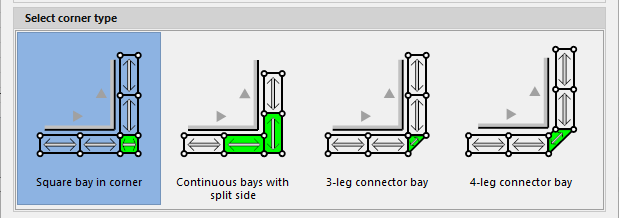
| Square Bay in Corner | This corner uses a square systems bay to connect the bays that follow adjoining walls. If the walls do not meet at a 90 degree angle, Avontus Designer may automatically substitute a connector bay . |
| Continuous Bays with Split Side | This corner uses two systems bays with seven standards. Avontus Designer shortens guardrails and ledgers for one of the bays and will attach them to the standard closest to the wall corner. |
| 3-Leg Connector Bay | This corner uses a connector bay with a shared standard. Avontus Designer uses systems ledgers and bracing for this bay whenever possible, but often substitutes tube and clamp materials automatically. |
| 4-Leg Connector Bay | This corner uses a connector bay with four standards. Avontus Designer uses systems ledgers and bracing for this bay whenever possible, but may often substitute tube and clamp materials automatically. |
Kwikstage Scaffold
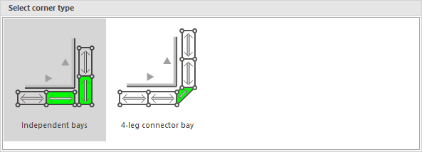
| Independent Bays | This corner uses two systems bays with an allowable gap between the bays. Avontus Designer planks this gap using wood planks as available in the Material Master. |
| 4-Leg Connector Bay | This corner uses a connector bay with four standards. Ledgers and bracing for this bay will automatically use tube and clamp materials. |