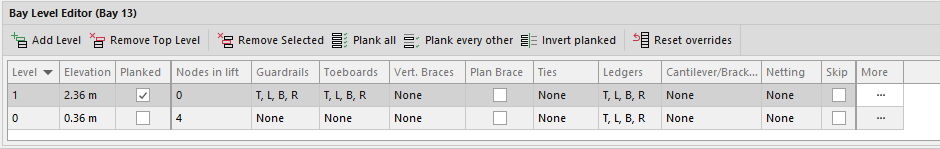
The Bay Level Editor contains settings and controls for a selected Bay and enables level-by-level editing. The details and settings for a specific Bay appear when you select that Bay in the Drawing Page.
Bay Level Editor Controls
Controls in the Bay Level Editor include:
| Add Level | Add a level to the top of a Bay. |
| Remove Top Level | Removes the top level of a Bay |
| Remove Selected | Removes the level selected in the grid for the Bay. |
| Plank All | Adds planks to every level of a Bay. |
| Plank Every Other | Adds planks to every other level of a Bay. Defaults to odd numbered levels. |
| Invert Planked | Adds planks to the currently non-planked levels and removes the planks from the currently planked levels. |
| Reset Overrides | Removes changes made to the Bay. |
| More | Additional controls, such as Guardrail Type, Toeboard Type, and Vert. Brace Direction. For additional information about this option, refer to the next section below below. |


For information about editing all levels of a Bay, and editing multiple Bays at once, refer to Bay Details Dropdown or Editing Bays Using Side Settings.
Tip: To unplank all Bays, select Plank All then click Invert Planked.
Bay Level Editor More Controls
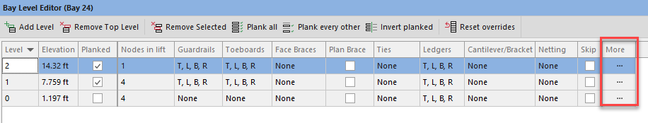
The More control in the Bay Level Editor provides additional options for editing Bay levels and materials. This also allows you to edit a specific Bay. Select on the More button for Level 1 will display the More details for that level.
Note: To edit all levels of a Bay at once, refer to Bay Details Dropdown or Editing Bays Using Side Settings.
Note: To edit all levels of a Bay at once, refer to Bay Details Dropdown or Editing Bays Using Side Settings.
The Level Tab
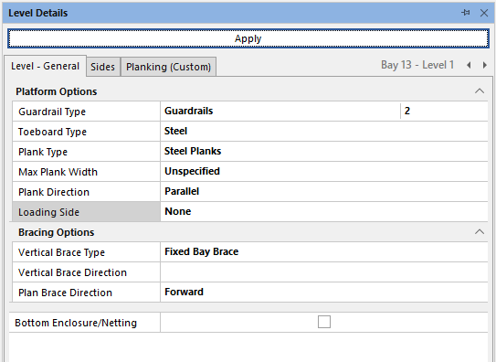
Avontus Designer will apply options you configure in the Level tab to all sides of the selected level, where applicable.
Guardrail Type | Use the Guardrail Type dropdown to determine the default guardrail configuration for the Bay. Your options are:
Use the numbered selection box to specify how many Guardrails you want added to this level |
Toeboard Type | Use the Toeboard Type dropdown to determine the default toeboards for the Bay. Options include:
|
Plank Type | Use the Plank Type dropdown to determine the default plank (deck) materials. Options include:
|
Plank Direction | Use the Plank Direction dropdown to determine the direction of the planks.
|
Loading Side | Use the Loading Side dropdown to determine the loading side. Your options are:
|
Vertical Brace Type | Use the Vertical Brace Type dropdown to determine the type of Vertical Brace.
|
Vertical Brace Direction | Use the Vertical Brace Direction dropdown to determine the Vertical Brace direction.
|
Plan Brace Type | Use the Plan Brace Type dropdown to determine the type of Plan Brace Type.
|
Plan Brace Direction | Use the Plan Brace Direction dropdown to determine the Plan Brace direction.
|
Stairway Direction | The direction of the staircase
Note: Only available on staircases |
Inner Handrail | Enable or disable the inner handrail Note: Only available on staircases |
Outer Hand Rail | Enable or disable the outer handrail Note: Only available on staircases |
Bottom Enclosure/Netting | Add bottom enclosure or netting to the selected level |
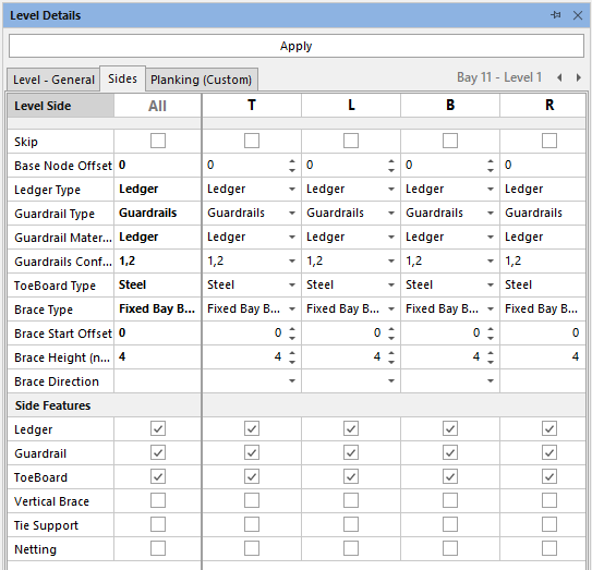
The Sides Tab
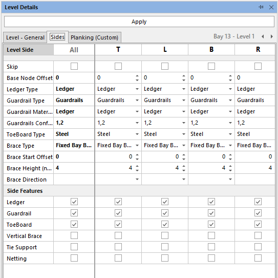
Avontus Designer applies options in the Sides tab to the selected side of the selected level, where applicable.
Skip | Select the checkbox to skip the Top, Left, Bottom, Right or all Sides |
Base Node Offset | This option is related to the Base Node Elevation, and is used to set the point in which the base node elevation will be measured against. |
Ledger Type | Use the Ledger Type dropdown to determine the ledger material for the selected Bay. Your options include:
|
Guardrail Type | Use the Guardrail Type dropdown to determine the default guardrail configuration for the Bay. Your options include:
|
Guardrail Material | Use the Guardrail Material dropdown to determine the guardrail material for the selected Bay. Your options include: Ledger (default)
|
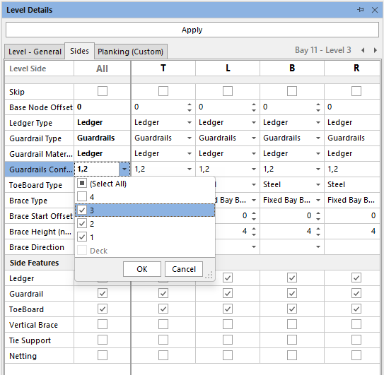
Guardrails Config | Select to enable or skip guardrails on a side or all sides of the bay, |
Toeboard Type | Use the Toeboard Type dropdown to determine the toeboard materials. Your options include:
|
Brace Type | Use the Brace Type dropdown to determine the brace materials. Your options include:
|
Brace Start Offset | This option is related to the Base Node Elevation, and is used to set the point in which the base start offset will be measured against. |
Brace Height (nodes) | Use the Brace Height text fields to determine the height (in nodes, up to 20 nodes) for any face brace for the selected Bay. |
Brace Direction | Use the Brace Direction dropdown to determine the brace direction for the selected Bay. Your options include:
|
Lower Section Checkboxes | Use the lower section checkboxes to enable or disable the available options to add or remove materials to the selected Bay side. Your options include:
|
Planking (Custom)
In the Bay Details, you can apply custom planking to the selected Bay. This allows you to select specific planks for a bay; for example, you could set Avontus Designer to use only planks from Scafom Rux for a specific Bay.
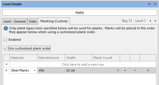
Enabled | Select the checkbox to enable custom planking options |
Use Customised Plank Order | Select this checkbox to enable the Plank Count column which will allow users to specify the number the planks to use. |
Material | Select the material to use for this bay |
Manufactuer | Select the manufactuer |
Width | Select the width of the Bay (these are taken from the Materal Master) |
Plank Count | Specify the number of planks for each custom planking. |
Editing individual Bays In the More screen
Using the arrow keys next to the Bay number, you can cycle through the Bay Level allowing you to apply changes on a specific Bay Level.
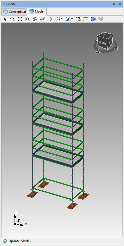
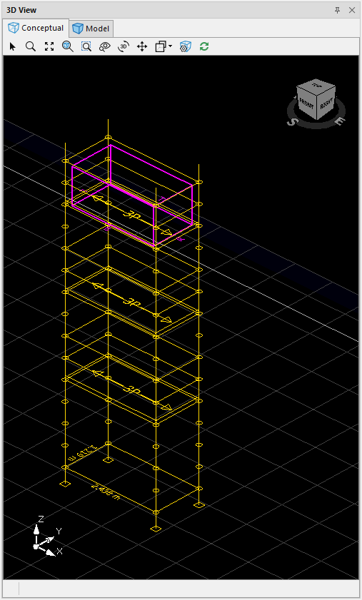
When you are editing an individual bay, you can see this reflected in the Conceptual view.
In a 3-level Bay, from the second level, selecting the right arrow will change the window to the third level
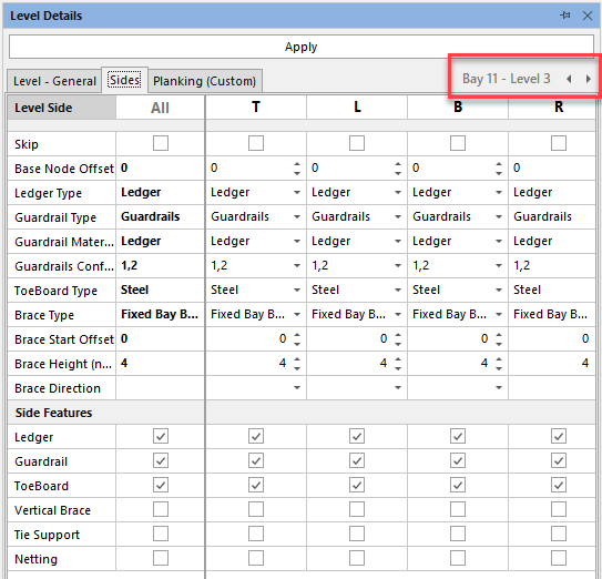
Whilst clicking the left arrow will change the window to the first level
You can then apply changes to a specific level. For example, we will add three guardrails to the top (third) level only.
You can see this change reflected in the 3D model